


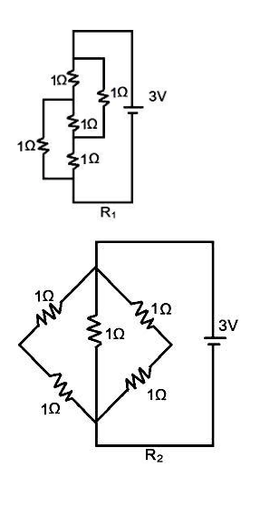
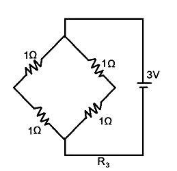
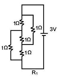
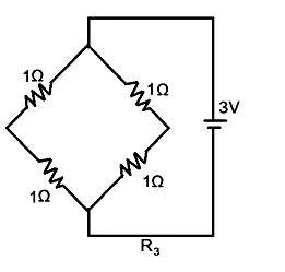
The three resistors configuration ${R_1},{R_2}$ and ${R_3}$ are connected to $3V$ battery as shown in figure. The power dissipated by the configuration ${R_1},{R_2}$ and ${R_3}$ is ${P_1},{P_2}$ and ${P_3}$ respectively. Then –
A) ${P_1} > {P_2} > {P_3}$
B) ${P_1} > {P_3} > {P_2}$
C) ${P_2} > {P_1} > {P_3}$
D) ${P_3} > {P_2} > {P_1}$
Answer
570.6k+ views
Hint: -Find the equivalent resistances for all the configurations in ${R_1},{R_2}$ and ${R_3}$. Now, by using the relation between power and resistance we will find the order of power in different configurations.
Complete Step by Step Solution: -
In the first configuration of ${R_1}$,
From this configuration, we can conclude that there is an equivalent wheatstone bridge circuit.
$\therefore \dfrac{{1\Omega }}{{1\Omega }} = \dfrac{{1\Omega }}{{1\Omega }} = 1\Omega $
Therefore, the equivalent resistance in the configuration ${R_1}$ is $1\Omega $.
Now, we have to calculate the equivalent resistance in the configuration ${R_2}$ -
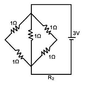
From the above figure, the equivalent resistance can be calculated by –
\[
\Rightarrow {R_2} = {\left( {\dfrac{1}{{1 + 1}} + 1 + \dfrac{1}{{1 + 1}}} \right)^{ - 1}} \\
\therefore {R_2} = {2^{ - 1}} = 0.5\Omega \\
\]
Therefore, the equivalent resistance in the configuration ${R_2}$ is $0.5\Omega $.
Now, we have to calculate the equivalent resistance in the configuration ${R_3}$ -
From the above figure, the equivalent resistance for the configuration ${R_3}$ is –
$
\Rightarrow {R_3} = 1 + \dfrac{{\left( {1 + 1} \right)\left( {1 + 1} \right)}}{{\left( {1 + 1} \right) + \left( {1 + 1} \right)}} \\
\therefore {R_3} = 1 + 1 = 2\Omega \\
$
Therefore, the equivalent resistance in the configuration ${R_3}$ is $2\Omega $.
We know that, relationship between power, voltage and resistance is –
$ \Rightarrow P = \dfrac{{{V^2}}}{R}$
So, the power ${P_1}$ for configuration ${R_1}$ is –
$ \Rightarrow {P_1} = \dfrac{{{3^2}}}{1} = 9W$
Power ${P_2}$ for configuration ${R_2}$ is –
$
{P_2} = \dfrac{{{3^2}}}{{0.5}} = \dfrac{9}{{0.5}} \\
\therefore {P_2} = 18W \\
$
Power ${P_3}$ for configuration ${R_3}$ is –
\[
{P_3} = \dfrac{{{3^2}}}{2} = \dfrac{9}{2} \\
\therefore {P_3} = 4.5W \\
\]
Now, we have calculated the power for each configuration for ${R_1},{R_2}$ and ${R_3}$ which are –
$
\Rightarrow {P_1} = 9W \\
\Rightarrow {P_2} = 18W \\
\Rightarrow {P_3} = 4.5W \\
$
Therefore, we can conclude that –
${P_2} > {P_1} > {P_3}$
Hence, the correct option is (C).
Note: -Wheatstone bridge is the circuit which is connected in form of the bridge and is composed of two known resistors, one unknown resistor and one variable resistor connected in the form of a bridge. This bridge gives accurate measurements, so it is most reliable. This bridge is used for the precise measurement of low resistance and is also used to measure inductance, capacitance and impedance by using the variations.
Complete Step by Step Solution: -
In the first configuration of ${R_1}$,
From this configuration, we can conclude that there is an equivalent wheatstone bridge circuit.
$\therefore \dfrac{{1\Omega }}{{1\Omega }} = \dfrac{{1\Omega }}{{1\Omega }} = 1\Omega $
Therefore, the equivalent resistance in the configuration ${R_1}$ is $1\Omega $.
Now, we have to calculate the equivalent resistance in the configuration ${R_2}$ -
From the above figure, the equivalent resistance can be calculated by –
\[
\Rightarrow {R_2} = {\left( {\dfrac{1}{{1 + 1}} + 1 + \dfrac{1}{{1 + 1}}} \right)^{ - 1}} \\
\therefore {R_2} = {2^{ - 1}} = 0.5\Omega \\
\]
Therefore, the equivalent resistance in the configuration ${R_2}$ is $0.5\Omega $.
Now, we have to calculate the equivalent resistance in the configuration ${R_3}$ -
From the above figure, the equivalent resistance for the configuration ${R_3}$ is –
$
\Rightarrow {R_3} = 1 + \dfrac{{\left( {1 + 1} \right)\left( {1 + 1} \right)}}{{\left( {1 + 1} \right) + \left( {1 + 1} \right)}} \\
\therefore {R_3} = 1 + 1 = 2\Omega \\
$
Therefore, the equivalent resistance in the configuration ${R_3}$ is $2\Omega $.
We know that, relationship between power, voltage and resistance is –
$ \Rightarrow P = \dfrac{{{V^2}}}{R}$
So, the power ${P_1}$ for configuration ${R_1}$ is –
$ \Rightarrow {P_1} = \dfrac{{{3^2}}}{1} = 9W$
Power ${P_2}$ for configuration ${R_2}$ is –
$
{P_2} = \dfrac{{{3^2}}}{{0.5}} = \dfrac{9}{{0.5}} \\
\therefore {P_2} = 18W \\
$
Power ${P_3}$ for configuration ${R_3}$ is –
\[
{P_3} = \dfrac{{{3^2}}}{2} = \dfrac{9}{2} \\
\therefore {P_3} = 4.5W \\
\]
Now, we have calculated the power for each configuration for ${R_1},{R_2}$ and ${R_3}$ which are –
$
\Rightarrow {P_1} = 9W \\
\Rightarrow {P_2} = 18W \\
\Rightarrow {P_3} = 4.5W \\
$
Therefore, we can conclude that –
${P_2} > {P_1} > {P_3}$
Hence, the correct option is (C).
Note: -Wheatstone bridge is the circuit which is connected in form of the bridge and is composed of two known resistors, one unknown resistor and one variable resistor connected in the form of a bridge. This bridge gives accurate measurements, so it is most reliable. This bridge is used for the precise measurement of low resistance and is also used to measure inductance, capacitance and impedance by using the variations.
Recently Updated Pages
Master Class 12 Economics: Engaging Questions & Answers for Success
Master Class 12 Physics: Engaging Questions & Answers for Success
Master Class 12 English: Engaging Questions & Answers for Success
Master Class 12 Social Science: Engaging Questions & Answers for Success
Master Class 12 Maths: Engaging Questions & Answers for Success
Master Class 12 Business Studies: Engaging Questions & Answers for Success
Trending doubts
Which are the Top 10 Largest Countries of the World?
What are the major means of transport Explain each class 12 social science CBSE
Draw a labelled sketch of the human eye class 12 physics CBSE
Why cannot DNA pass through cell membranes class 12 biology CBSE
Differentiate between insitu conservation and exsitu class 12 biology CBSE
Draw a neat and well labeled diagram of TS of ovary class 12 biology CBSE