


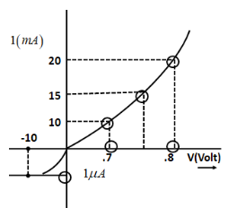
The V-I characteristics of a diode are shown in the figure. The ratio of forward to reverse bias resistance is:
A. \[100\]
B. \[{10^{ - 6}}\]
C. \[10\]
D. \[{10^6}\]
Answer
566.4k+ views
Hint:The forward I-V characteristic, that is when the diode is forward biased, the anode is positive with respect to cathode. They given when the current is positive and the voltage is also positive. On the other hand, the reverse I-V characteristics are given when the cathode is positive with respect to anode. Here, the current is positive and the voltage is negative.
Formula Used:
Forward bias resistance \[{R_f}\] is given as:\[{R_f} = \dfrac{{\Delta {V_f}}}{{\Delta {I_f}}}\]
where,\[\Delta {V_f}\]is the difference between forward bias voltages,
\[\Delta {I_f}\] is the difference between currents corresponding to particular forward bias voltages.
Reverse bias resistance \[{R_r}\] is given as:\[{R_r} = \dfrac{{\Delta {V_r}}}{{\Delta {I_r}}}\]
where,\[\Delta {V_r}\]is the difference between reverse bias voltages,
\[\Delta {I_r}\] is the difference between currents corresponding to particular reverse bias voltages.
Complete step by step answer:
The resistance offered by a diode in forward bias is very small. This is called forward resistance. On the other hand, a diode offers very high resistance when it is in reverse bias.This is called reverse resistance.
The formula for forward bias resistance \[{R_f}\] is given as:
\[{R_f} = \dfrac{{\Delta {V_f}}}{{\Delta {I_f}}}\]\[ \to \]................(1)
where,\[\Delta {V_f}\]is the difference between forward bias voltages and \[\Delta {I_f}\] is the difference between currents corresponding to particular voltages.
From the given diagram, the voltages run from 0.7 Volts to 0.8 Volts. On the other hand, current ranges from 10 to 20 milli-Amperes. Therefore,
\[\Delta {I_f} = 20 - 10 \\
\Rightarrow \Delta {I_f} = 10mA \\
\Rightarrow \Delta {I_f} = 10 \times {10^{ - 3}}A\]
\[\Rightarrow \Delta {V_f} = 0.8 - 0.7 \\
\Rightarrow \Delta {V_f} = 0.1V\]
Substituting in equation (1)
\[{R_f} = \dfrac{{\Delta {V_f}}}{{\Delta {I_f}}} \\
\Rightarrow {R_f} = \dfrac{{0.1}}{{10 \times {{10}^{ - 3}}}}\Omega \\
\Rightarrow {R_f} = 10\Omega \]
The formula for reverse bias resistance \[{R_r}\] is given as:
\[{R_r} = \dfrac{{\Delta {V_r}}}{{\Delta {I_r}}}\]\[ \to \]................(2)
where,\[\Delta {V_r}\]is the difference between reverse bias voltages and \[\Delta {I_r}\] is the difference between currents corresponding to particular voltages.
Also according to the diagram, the reverse bias current will be
\[{R_r} = \dfrac{{\Delta {V_r}}}{{\Delta {I_r}}} \\
\Rightarrow {R_r} = \dfrac{{10}}{{{{10}^{ - 6}}}}\Omega \\
\Rightarrow {R_r} = {10^7}\Omega \]
Then, the ratio of forward bias to reverse bias resistance can be written as:
\[Ratio = \dfrac{{{R_f}}}{{{R_r}}} \\
\Rightarrow Ratio = \dfrac{{10}}{{{{10}^7}}}\Omega \\
\therefore Ratio = {10^{ - 6}}\Omega \]
Hence, option B is the correct answer.
Note:The formula for reverse bias resistance and forward bias resistance can be written with the help of Ohm’s Law. Ohm’s law is given by
\[V = IR\]
where \[V\] is the voltage, \[I\] is the current and \[R\] is the resistance.
Thus, resistance can be written as \[R = \dfrac{V}{I}\]
Thus if one writes independently in terms of forward and reverse bias resistance, this equation is,
\[{R_r} = \dfrac{{\Delta {V_r}}}{{\Delta {I_r}}}\]
And \[{R_r} = \dfrac{{\Delta {V_r}}}{{\Delta {I_r}}}\] respectively.
Recently Updated Pages
Master Class 12 Economics: Engaging Questions & Answers for Success
Master Class 12 Physics: Engaging Questions & Answers for Success
Master Class 12 English: Engaging Questions & Answers for Success
Master Class 12 Social Science: Engaging Questions & Answers for Success
Master Class 12 Maths: Engaging Questions & Answers for Success
Master Class 12 Business Studies: Engaging Questions & Answers for Success
Trending doubts
Which are the Top 10 Largest Countries of the World?
What are the major means of transport Explain each class 12 social science CBSE
Draw a labelled sketch of the human eye class 12 physics CBSE
Why cannot DNA pass through cell membranes class 12 biology CBSE
Differentiate between insitu conservation and exsitu class 12 biology CBSE
Draw a neat and well labeled diagram of TS of ovary class 12 biology CBSE