


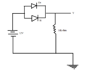
Two junction diodes one of germanium ( Ge ) and another of silicon (Si ) are connected as shown in the figure to a battery of emf $12V$ and a load resistance $10k\Omega $. The germanium diode conducts at $0.3V$ and silicon diode at $0.7V$. When a current flows in the circuit, then the potential of terminal $Y$will be:
$\begin{align}
& A)12V \\
& B)11V \\
& C)11.3V \\
& D)11.7V \\
\end{align}$
Answer
601.5k+ views
Hint: Students can apply the concept of Kirchoff’s voltage law to determine the potential at terminal $Y$. Both the diodes given in the question are forward biased, as a result of which they will allow the flow of current through the circuit. Current always takes the shortest possible path while moving through a circuit.
Complete step by step solution:
In the given circuit, both the germanium and silicon diodes are forward biased, that is they allow the flow of current through them. Now as the circuit is switched on, current will start flowing across the circuit, starting from the battery towards the diodes. As it has been already mentioned in the question that the Si diode conducts at $0.7V$ and the Ge diode conducts at $0.3V$.
So, as current passes through the circuit and reaches the Ge diode, there will be a voltage drop across the diode and current will flow through it, but in the case of Si, as it conducts only at $0.7V$, so it will require $0.4V$more than the Ge diode, so as to undergo voltage drop and to make current flow through the circuit. As Ge diode attains $0.3V$, it becomes short circuited.
Now, the voltage at terminal $Y$ will be because of the current flowing through the Ge diode.
By using Kirchhoff's Voltage law (KVL),
If the voltage at the terminal $Y$is taken to be $v$ , then
$\begin{align}
& 12-0.3-v=0 \\
& \Rightarrow v=12-0.3 \\
& \Rightarrow v=11.7V \\
\end{align}$
Therefore the voltage at terminal $Y$ is $11.7V$.
The answer is option $D)11.7V$.
Note: In this particular circuit, students must not get confused as to which law to be used, KVL or KCL (Kirchoff’s Current Law). This question has provided us the information regarding the voltages across the different parts of the circuit, so it is always preferable to use the KVL rather than KCL. Students must also pay attention to the fact that current follows always the shortest possible path.
Recently Updated Pages
Master Class 12 Economics: Engaging Questions & Answers for Success
Master Class 12 Physics: Engaging Questions & Answers for Success
Master Class 12 English: Engaging Questions & Answers for Success
Master Class 12 Social Science: Engaging Questions & Answers for Success
Master Class 12 Maths: Engaging Questions & Answers for Success
Master Class 12 Business Studies: Engaging Questions & Answers for Success
Trending doubts
Which are the Top 10 Largest Countries of the World?
What are the major means of transport Explain each class 12 social science CBSE
Draw a labelled sketch of the human eye class 12 physics CBSE
Why cannot DNA pass through cell membranes class 12 biology CBSE
Differentiate between insitu conservation and exsitu class 12 biology CBSE
Draw a neat and well labeled diagram of TS of ovary class 12 biology CBSE