With the help neat labeled circuit diagram explain the working of half wave rectifier using semiconductor diode. Draw the input and output waveforms.
Answer
568.5k+ views
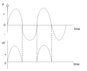
Hint: In this question we have to explain all the steps of working of half wave rectifier. Without diagram we can't explain clearly. A half wave rectifier is nothing but removes the negative half cycle of an AC input and allows only the positive cycles to pass creating a DC flow this conversion happens with the help of using semiconductor diodes.
Complete answer:
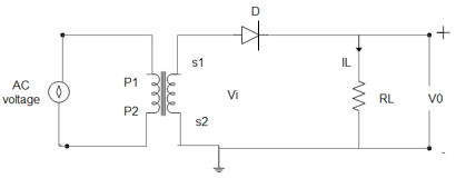
To understand the working of a half wave rectifier perfectly we must know the theory part really well. For this we have to know the concepts of a PN junction and its characteristics. The working of a half wave rectifier is pretty simple. From the theory part we should know that a pn junction diode conducts current only in 1 direction. In simple words a pn junction diode conducts current only when it is forward biased this principle is made use of in a half wave rectifier to convert AC to DC. The input we give here is an alternating current i.e AC here this input voltage is stepped down using a transformer as shown in figure. This reduced voltage is fed to the diode ‘D’ and load resistance RL during the positive half cycles of the input wave. The diode ‘D’ will be forward biased and during the negative half cycles of input wave the diode ‘D’ will be reverse. A current IL passes through the load resistance RL in the direction shown in the diagram. During the next half cycle when the p-region is negative the diode is reverse biased and the forward current drops to zero. Thus the diode conducts only during an half of the input cycle and thus acts as a half wave rectifier.
Vl is the input voltage which is the alternating voltage.
D is the semiconductor diode.
P1 and P2 are the primary region of the coil.
S1 and S2 are the secondary region of the coil.
RL is the load resistance.
V0 is the output voltage.


Note:
A half wave rectification is an application of the pn junction diode. So to understand the half wave rectifier theory we need to understand the pn junction and the characteristics of the pn junction diode. We have to practice both diagrams and input –output graphs.
Complete answer:
To understand the working of a half wave rectifier perfectly we must know the theory part really well. For this we have to know the concepts of a PN junction and its characteristics. The working of a half wave rectifier is pretty simple. From the theory part we should know that a pn junction diode conducts current only in 1 direction. In simple words a pn junction diode conducts current only when it is forward biased this principle is made use of in a half wave rectifier to convert AC to DC. The input we give here is an alternating current i.e AC here this input voltage is stepped down using a transformer as shown in figure. This reduced voltage is fed to the diode ‘D’ and load resistance RL during the positive half cycles of the input wave. The diode ‘D’ will be forward biased and during the negative half cycles of input wave the diode ‘D’ will be reverse. A current IL passes through the load resistance RL in the direction shown in the diagram. During the next half cycle when the p-region is negative the diode is reverse biased and the forward current drops to zero. Thus the diode conducts only during an half of the input cycle and thus acts as a half wave rectifier.
Vl is the input voltage which is the alternating voltage.
D is the semiconductor diode.
P1 and P2 are the primary region of the coil.
S1 and S2 are the secondary region of the coil.
RL is the load resistance.
V0 is the output voltage.


Note:
A half wave rectification is an application of the pn junction diode. So to understand the half wave rectifier theory we need to understand the pn junction and the characteristics of the pn junction diode. We have to practice both diagrams and input –output graphs.
Recently Updated Pages
Master Class 12 Economics: Engaging Questions & Answers for Success

Master Class 12 Physics: Engaging Questions & Answers for Success

Master Class 12 English: Engaging Questions & Answers for Success

Master Class 12 Social Science: Engaging Questions & Answers for Success

Master Class 12 Maths: Engaging Questions & Answers for Success

Master Class 12 Business Studies: Engaging Questions & Answers for Success

Trending doubts
Which are the Top 10 Largest Countries of the World?

What are the major means of transport Explain each class 12 social science CBSE

Draw a labelled sketch of the human eye class 12 physics CBSE

Why cannot DNA pass through cell membranes class 12 biology CBSE

Differentiate between insitu conservation and exsitu class 12 biology CBSE

Draw a neat and well labeled diagram of TS of ovary class 12 biology CBSE


