


Write Kirchhoff’s first rule (law of junction). Drawing a circuit diagram of Wheatstone bridge, derive condition for zero deflection in the bridge.
Answer
598.2k+ views
Hint: Kirchhoff’s first rule (law of junction) is completely based on the law of conservation of charge. Deflection in bridge is calculated by a Galvanometer, it shows zero reading when there is no voltage between the ends. Hence the voltage ${V_o}$ would be zero.
Useful formula:
Ohm’s law is given by,
$V = IR$
Where, \[V\] is the voltage between the resistors, $I$ is the current through the resistor and $R$ is the resistance of the resistor.
Complete step by step solution:
Kirchhoff’s first rule:
Kirchhoff’s first rule (law of junction) states that in an electrical circuit, the algebraic total of current which enters the junction is equal to the algebraic total of current which exits the junction. It is based on the law of conservation of charge.
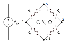
Assume that,
Voltage at point A is ${V_A}$
Voltage at point B is ${V_B}$
Voltage at point 1 is ${V_1}$
Voltage at point 2 is ${V_2}$
Voltage through resistor ${R_1}$ is ${V_{R1}}$
Voltage through resistor ${R_2}$ is ${V_{R2}}$
Voltage through resistor ${R_3}$ is ${V_{R3}}$
Voltage through resistor ${R_4}$ is ${V_{R4}}$
Current through resistor ${R_1}$ is ${I_1}$
Current through resistor ${R_2}$ is ${I_2}$
Current through resistor ${R_3}$ is ${I_3}$
Current through resistor ${R_4}$ is ${I_4}$
For zero deflection in the galvanometer, the voltage ${V_0}$ would be zero.
Hence,
Voltage at point 1 = Voltage at point 2
${V_1} = {V_2}\;........................................\left( 1 \right)$
So, the current passing through the galvanometer is zero.
Hence,
Current through ${R_1}$ = Current through ${R_2}$
${I_1} = {I_2}\;........................\left( 2 \right)$
By using Ohm’s law,
Current through resistor ${R_1}$, ${I_1} = \dfrac{{{V_{R1}}}}{{{R_1}}}$
Since, ${V_{R1}} = {V_1} - {V_A}$
Thus, ${I_1} = \dfrac{{{V_1} - {V_A}}}{{{R_1}}}$
Current through resistor ${R_2}$, ${I_2} = \dfrac{{{V_{R2}}}}{{{R_2}}}$
Since, ${V_{R2}} = {V_1} - {V_B}$
Thus, ${I_2} = \dfrac{{{V_1} - {V_B}}}{{{R_2}}}$
Substitute the values of ${I_1}$ and ${I_2}$ in equation (2),
$\dfrac{{\left( {{V_1} - {V_A}} \right)}}{{{R_1}}} = \dfrac{{\left( {{V_1} - {V_B}} \right)}}{{{R_2}}}\;..............................\left( 3 \right)$
Similarly,
${I_4} = {I_3}\;........................\left( 4 \right)$
Current through resistor ${R_4}$, ${I_4} = \dfrac{{{V_{R4}}}}{{{R_4}}}$
Since, ${V_{R4}} = {V_2} - {V_A}$
Thus, ${I_4} = \dfrac{{{V_2} - {V_A}}}{{{R_4}}}$
Current through resistor ${R_3}$, ${I_3} = \dfrac{{{V_{R3}}}}{{{R_3}}}$
Since, ${V_{R3}} = {V_2} - {V_B}$
Thus, ${I_3} = \dfrac{{{V_2} - {V_B}}}{{{R_3}}}$
Substitute the values of ${I_4}$ and ${I_3}$ in equation (4),
$\dfrac{{\left( {{V_2} - {V_A}} \right)}}{{{R_4}}} = \dfrac{{\left( {{V_2} - {V_B}} \right)}}{{{R_3}}}\;..............................\left( 5 \right)$
Dividing the equation (5) from (3),
$
\dfrac{{\dfrac{{\left( {{V_2} - {V_A}} \right)}}{{{R_4}}}}}{{\dfrac{{\left( {{V_1} - {V_A}} \right)}}{{{R_1}}}}} = \dfrac{{\dfrac{{\left( {{V_2} - {V_B}} \right)}}{{{R_3}}}}}{{\dfrac{{\left( {{V_1} - {V_B}} \right)}}{{{R_2}}}}} \\
\dfrac{{\left( {{V_2} - {V_A}} \right)}}{{{R_4}}} \times \dfrac{{{R_1}}}{{\left( {{V_1} - {V_A}} \right)}} = \dfrac{{\left( {{V_2} - {V_B}} \right)}}{{{R_3}}} \times \dfrac{{{R_2}}}{{\left( {{V_1} - {V_B}} \right)}} \\
\\
$
By equation (1),
${V_1} = {V_2}\;$
Thus,
$
\dfrac{{\left( {{V_1} - {V_A}} \right)}}{{{R_4}}} \times \dfrac{{{R_1}}}{{\left( {{V_1} - {V_A}} \right)}} = \dfrac{{\left( {{V_1} - {V_B}} \right)}}{{{R_3}}} \times \dfrac{{{R_2}}}{{\left( {{V_1} - {V_B}} \right)}} \\
\dfrac{{{R_1}}}{{{R_4}}} = \dfrac{{{R_2}}}{{{R_3}}} \\
$
Hence, the above condition is the necessary and required condition for the voltage across the bridge ${V_o} = 0$.
Note: The voltage between the bridge is equal to zero, when the potential between the points 1 and 2 must be zero. Hence the combination of the resistor is very much important. The ratio between the opposite resistance is equal to another side ratio between the opposite resistance. Hence, the combination must be accurate.
Useful formula:
Ohm’s law is given by,
$V = IR$
Where, \[V\] is the voltage between the resistors, $I$ is the current through the resistor and $R$ is the resistance of the resistor.
Complete step by step solution:
Kirchhoff’s first rule:
Kirchhoff’s first rule (law of junction) states that in an electrical circuit, the algebraic total of current which enters the junction is equal to the algebraic total of current which exits the junction. It is based on the law of conservation of charge.
Assume that,
Voltage at point A is ${V_A}$
Voltage at point B is ${V_B}$
Voltage at point 1 is ${V_1}$
Voltage at point 2 is ${V_2}$
Voltage through resistor ${R_1}$ is ${V_{R1}}$
Voltage through resistor ${R_2}$ is ${V_{R2}}$
Voltage through resistor ${R_3}$ is ${V_{R3}}$
Voltage through resistor ${R_4}$ is ${V_{R4}}$
Current through resistor ${R_1}$ is ${I_1}$
Current through resistor ${R_2}$ is ${I_2}$
Current through resistor ${R_3}$ is ${I_3}$
Current through resistor ${R_4}$ is ${I_4}$
For zero deflection in the galvanometer, the voltage ${V_0}$ would be zero.
Hence,
Voltage at point 1 = Voltage at point 2
${V_1} = {V_2}\;........................................\left( 1 \right)$
So, the current passing through the galvanometer is zero.
Hence,
Current through ${R_1}$ = Current through ${R_2}$
${I_1} = {I_2}\;........................\left( 2 \right)$
By using Ohm’s law,
Current through resistor ${R_1}$, ${I_1} = \dfrac{{{V_{R1}}}}{{{R_1}}}$
Since, ${V_{R1}} = {V_1} - {V_A}$
Thus, ${I_1} = \dfrac{{{V_1} - {V_A}}}{{{R_1}}}$
Current through resistor ${R_2}$, ${I_2} = \dfrac{{{V_{R2}}}}{{{R_2}}}$
Since, ${V_{R2}} = {V_1} - {V_B}$
Thus, ${I_2} = \dfrac{{{V_1} - {V_B}}}{{{R_2}}}$
Substitute the values of ${I_1}$ and ${I_2}$ in equation (2),
$\dfrac{{\left( {{V_1} - {V_A}} \right)}}{{{R_1}}} = \dfrac{{\left( {{V_1} - {V_B}} \right)}}{{{R_2}}}\;..............................\left( 3 \right)$
Similarly,
${I_4} = {I_3}\;........................\left( 4 \right)$
Current through resistor ${R_4}$, ${I_4} = \dfrac{{{V_{R4}}}}{{{R_4}}}$
Since, ${V_{R4}} = {V_2} - {V_A}$
Thus, ${I_4} = \dfrac{{{V_2} - {V_A}}}{{{R_4}}}$
Current through resistor ${R_3}$, ${I_3} = \dfrac{{{V_{R3}}}}{{{R_3}}}$
Since, ${V_{R3}} = {V_2} - {V_B}$
Thus, ${I_3} = \dfrac{{{V_2} - {V_B}}}{{{R_3}}}$
Substitute the values of ${I_4}$ and ${I_3}$ in equation (4),
$\dfrac{{\left( {{V_2} - {V_A}} \right)}}{{{R_4}}} = \dfrac{{\left( {{V_2} - {V_B}} \right)}}{{{R_3}}}\;..............................\left( 5 \right)$
Dividing the equation (5) from (3),
$
\dfrac{{\dfrac{{\left( {{V_2} - {V_A}} \right)}}{{{R_4}}}}}{{\dfrac{{\left( {{V_1} - {V_A}} \right)}}{{{R_1}}}}} = \dfrac{{\dfrac{{\left( {{V_2} - {V_B}} \right)}}{{{R_3}}}}}{{\dfrac{{\left( {{V_1} - {V_B}} \right)}}{{{R_2}}}}} \\
\dfrac{{\left( {{V_2} - {V_A}} \right)}}{{{R_4}}} \times \dfrac{{{R_1}}}{{\left( {{V_1} - {V_A}} \right)}} = \dfrac{{\left( {{V_2} - {V_B}} \right)}}{{{R_3}}} \times \dfrac{{{R_2}}}{{\left( {{V_1} - {V_B}} \right)}} \\
\\
$
By equation (1),
${V_1} = {V_2}\;$
Thus,
$
\dfrac{{\left( {{V_1} - {V_A}} \right)}}{{{R_4}}} \times \dfrac{{{R_1}}}{{\left( {{V_1} - {V_A}} \right)}} = \dfrac{{\left( {{V_1} - {V_B}} \right)}}{{{R_3}}} \times \dfrac{{{R_2}}}{{\left( {{V_1} - {V_B}} \right)}} \\
\dfrac{{{R_1}}}{{{R_4}}} = \dfrac{{{R_2}}}{{{R_3}}} \\
$
Hence, the above condition is the necessary and required condition for the voltage across the bridge ${V_o} = 0$.
Note: The voltage between the bridge is equal to zero, when the potential between the points 1 and 2 must be zero. Hence the combination of the resistor is very much important. The ratio between the opposite resistance is equal to another side ratio between the opposite resistance. Hence, the combination must be accurate.
Recently Updated Pages
Master Class 12 Economics: Engaging Questions & Answers for Success
Master Class 12 Physics: Engaging Questions & Answers for Success
Master Class 12 English: Engaging Questions & Answers for Success
Master Class 12 Social Science: Engaging Questions & Answers for Success
Master Class 12 Maths: Engaging Questions & Answers for Success
Master Class 12 Business Studies: Engaging Questions & Answers for Success
Trending doubts
Which are the Top 10 Largest Countries of the World?
What are the major means of transport Explain each class 12 social science CBSE
Draw a labelled sketch of the human eye class 12 physics CBSE
Why cannot DNA pass through cell membranes class 12 biology CBSE
Differentiate between insitu conservation and exsitu class 12 biology CBSE
Draw a neat and well labeled diagram of TS of ovary class 12 biology CBSE