


Write the principle and explain the construction and working of a transformer. Define its efficiency.
Answer
593.1k+ views
Hint: The transformer is an electrical device used for the step-up or step-down of the incoming current value. It has one primary coil and one secondary coil. The primary coil takes the incoming current and gives the output voltage or current on the secondary coil.
Complete step-by-step answer:
Principle- transformer works on the principle known as electromagnetic induction. Electromagnetic induction is the phenomenon in which an induced emf is produced due to changes in the associated magnetic flux in a closed circuit.
Construction and working-
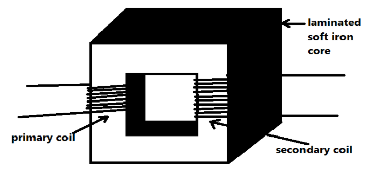
The transformer consists of a soft iron core. To minimize the eddy current losses this core is to be laminated. The primary and secondary coils are wound on the soft iron core (insulated from each other) as shown in the figure.
Now when the AC input is applied across the primary coil then a varying magnetic flux is produced in the primary coil, since AC current is always changing its direction continuously and have its function as a sine wave. Now, this varying magnetic field will produce another varying magnetic flux in the secondary coil. So due to this varying magnetic flux, an induced emf is produced in the secondary coil.
Let us make some assumptions for the symbols we will use further.
So, let ${E_p} = $induced emf in the primary coil.
${E_s} = $induced emf in the secondary coil.
${N_p} = $number of turns in the primary coil.
${N_s} = $ number of turns in the secondary coil.
Now from the working procedure, we know that the same flux is linked with both the primary and the secondary coil.
So, the induced emf power unit turns off the coil will be the same for both primary and the secondary coil of the transformer.
i.e. $\dfrac{{{E_p}}}{{{N_p}}} = \dfrac{{{E_s}}}{{{N_s}}}$
or we can also write like $\dfrac{{{E_p}}}{{{E_s}}} = \dfrac{{{N_p}}}{{{N_s}}}$
$ \Rightarrow \dfrac{{{E_s}}}{{{E_p}}} = \dfrac{{{N_s}}}{{{N_p}}}$------equation (1)
We also know that the power of any electrical circuit is the product of the voltage and the current. And here for an ideal transformer the input power will be equal to the output power.
So, for an ideal transformer,
${E_p}{I_p} = {E_s}{I_s}$
$ \Rightarrow \dfrac{{{E_p}}}{{{E_s}}} = \dfrac{{{I_s}}}{{{I_p}}}$
$ \Rightarrow \dfrac{{{E_s}}}{{{E_p}}} = \dfrac{{{I_p}}}{{{I_s}}}$-------equation (2)
So, from equation (1) and equation (2), we have come to the conclusion that,
$ \Rightarrow \dfrac{{{E_s}}}{{{E_p}}} = \dfrac{{{N_s}}}{{{N_p}}} = \dfrac{{{I_p}}}{{{I_s}}} = k$
Here the $k$ is known as the transformer ratio.
For the step-up transformer, $k > 1$and ${E_s} > {E_p}$ and ${I_s} < {I_p}$.
And for the step-down transformer, $k < 1$and ${E_p} > {E_s}$ and ${I_p} < {I_s}$
This shows that the step-up transformer will be used to increase the voltage while step-down will be used to decrease the voltage.
Now for the efficiency of the transformer,
As we know that efficiency is always the ratio of output and the input. So here the efficiency will be,
$\eta = \dfrac{{output{\text{ }}power}}{{input{\text{ }}power}} = \dfrac{{{E_s}{I_s}}}{{{E_p}{I_p}}}$
Note: Here we have considered that there are no losses. Here we have considered the ideal transformer. But we always get some losses in the practical aspects. So, there are some losses associated with the transformer. So, the losses related to the transformer are as follows,
(i). Copper loss
(ii). Hysteresis loss
(iii). Flux loss
(iv). Eddy current loss
Complete step-by-step answer:
Principle- transformer works on the principle known as electromagnetic induction. Electromagnetic induction is the phenomenon in which an induced emf is produced due to changes in the associated magnetic flux in a closed circuit.
Construction and working-
The transformer consists of a soft iron core. To minimize the eddy current losses this core is to be laminated. The primary and secondary coils are wound on the soft iron core (insulated from each other) as shown in the figure.
Now when the AC input is applied across the primary coil then a varying magnetic flux is produced in the primary coil, since AC current is always changing its direction continuously and have its function as a sine wave. Now, this varying magnetic field will produce another varying magnetic flux in the secondary coil. So due to this varying magnetic flux, an induced emf is produced in the secondary coil.
Let us make some assumptions for the symbols we will use further.
So, let ${E_p} = $induced emf in the primary coil.
${E_s} = $induced emf in the secondary coil.
${N_p} = $number of turns in the primary coil.
${N_s} = $ number of turns in the secondary coil.
Now from the working procedure, we know that the same flux is linked with both the primary and the secondary coil.
So, the induced emf power unit turns off the coil will be the same for both primary and the secondary coil of the transformer.
i.e. $\dfrac{{{E_p}}}{{{N_p}}} = \dfrac{{{E_s}}}{{{N_s}}}$
or we can also write like $\dfrac{{{E_p}}}{{{E_s}}} = \dfrac{{{N_p}}}{{{N_s}}}$
$ \Rightarrow \dfrac{{{E_s}}}{{{E_p}}} = \dfrac{{{N_s}}}{{{N_p}}}$------equation (1)
We also know that the power of any electrical circuit is the product of the voltage and the current. And here for an ideal transformer the input power will be equal to the output power.
So, for an ideal transformer,
${E_p}{I_p} = {E_s}{I_s}$
$ \Rightarrow \dfrac{{{E_p}}}{{{E_s}}} = \dfrac{{{I_s}}}{{{I_p}}}$
$ \Rightarrow \dfrac{{{E_s}}}{{{E_p}}} = \dfrac{{{I_p}}}{{{I_s}}}$-------equation (2)
So, from equation (1) and equation (2), we have come to the conclusion that,
$ \Rightarrow \dfrac{{{E_s}}}{{{E_p}}} = \dfrac{{{N_s}}}{{{N_p}}} = \dfrac{{{I_p}}}{{{I_s}}} = k$
Here the $k$ is known as the transformer ratio.
For the step-up transformer, $k > 1$and ${E_s} > {E_p}$ and ${I_s} < {I_p}$.
And for the step-down transformer, $k < 1$and ${E_p} > {E_s}$ and ${I_p} < {I_s}$
This shows that the step-up transformer will be used to increase the voltage while step-down will be used to decrease the voltage.
Now for the efficiency of the transformer,
As we know that efficiency is always the ratio of output and the input. So here the efficiency will be,
$\eta = \dfrac{{output{\text{ }}power}}{{input{\text{ }}power}} = \dfrac{{{E_s}{I_s}}}{{{E_p}{I_p}}}$
Note: Here we have considered that there are no losses. Here we have considered the ideal transformer. But we always get some losses in the practical aspects. So, there are some losses associated with the transformer. So, the losses related to the transformer are as follows,
(i). Copper loss
(ii). Hysteresis loss
(iii). Flux loss
(iv). Eddy current loss
Recently Updated Pages
Master Class 12 Economics: Engaging Questions & Answers for Success
Master Class 12 Physics: Engaging Questions & Answers for Success
Master Class 12 English: Engaging Questions & Answers for Success
Master Class 12 Social Science: Engaging Questions & Answers for Success
Master Class 12 Maths: Engaging Questions & Answers for Success
Master Class 12 Business Studies: Engaging Questions & Answers for Success
Trending doubts
Which are the Top 10 Largest Countries of the World?
What are the major means of transport Explain each class 12 social science CBSE
Draw a labelled sketch of the human eye class 12 physics CBSE
Why cannot DNA pass through cell membranes class 12 biology CBSE
Differentiate between insitu conservation and exsitu class 12 biology CBSE
Draw a neat and well labeled diagram of TS of ovary class 12 biology CBSE