CBSE Class 10 Chapter 11 Electricity Notes Class 10: FREE PDF Downloads
Vedantu Provides a comprehensive overview of CBSE Science Class 10 Physics Electricity Notes, breaking down complex concepts into easy-to-understand parts according to the Class 10 Science Syllabus. In this Note, Students will learn about electric current, voltage, resistance, and Ohm's Law in a clear and structured way. Class 10 Science Notes include detailed explanations, essential formulas, and practical examples to help you see how these concepts apply in real-world situations. Designed to support your studies, these notes will help you grasp the fundamentals of electricity, making exam preparation more effective and less stressful. With a focus on clarity and simplicity, you'll be well-equipped to understand questions and excel in your understanding of electrical principles.
Electricity Class 10 Notes: CBSE Science Chapter 11
Access Revision Notes for Class 10 Science Chapter 11 - Electricity
Introduction
The Greek words "Electrica" and "Elektron" were used to describe electricity.
Thales, a Greek philosopher, was the first to notice how certain elements attract other materials when rubbed together.
These materials were divided into two categories by Gilbert: vitreous and resinous, as Positive charges and Negative charges.
Frictional Electricity
Fur, flannel, wax, glass, cotton, paper, silk, human skin, wood, metals, rubber, resin, amber, sulphur, and ebonite are just a few of the materials used.
If any two materials in this series are rubbed together, the element that occurs initially in the series will get positive charge, while the element that occurs later in the series will gain a negative charge.
Fundamental Laws of Electrostatics
Positive and negative charges are the two types of charges.
Charges that are similar repel each other, while charges that are dissimilar attract each other.
Coulomb’s Law
\[\text{F }\alpha \text{ }\dfrac{\left( {{\text{q}}_{\text{1}}}{{\text{q}}_{\text{2}}} \right)}{{{\text{r}}^{\text{2}}}}\]
The electrostatic attraction or repulsion force between two charges is proportional to the product of their charges and inversely proportional to the square of their distance.
\[\text{F = }\dfrac{\left( \text{K}{{\text{q}}_{\text{1}}}{{\text{q}}_{\text{2}}} \right)}{{{\text{r}}^{\text{2}}}}\]
\[\text{K}\] is the constant of proportionality and is equal to \[\text{9 }\!\!\times\!\!\text{ 1}{{\text{0}}^{\text{9}}}\text{N}{{\text{m}}^{\text{2}}}\text{/}{{\text{C}}^{\text{2}}}\] for free space.
The force is repulsive for similar charges and attractive for dissimilar ones.
Charge Conservation
When an ebonite rod is brushed with fur, the ebonite gains a negative charge, while the fur gains a positive charge.
This indicates that electrons have transferred from fur to ebonite.
The system's net charge stays unchanged.
As a result, charges are not generated or destroyed; rather, they are moved from one material to another.
Insulators and Conductors
Insulators are poor conductors of electricity, yet they can be quickly charged through friction.
Charges can flow freely through conductors..
Current
The rate of charge flow is referred to as current.
If the charge \[\text{q}\] is in coulomb and \[\text{t}\] is the time in seconds then,
current is
\[\text{I = }\dfrac{\text{q}}{\text{t}}\]
The \[\text{SI}\] unit of current is ampere \[\left( \text{A} \right)\].
Current is a scalar quantity.
Example:
A current of \[1\text{A}\] is drawn by a filament of an electric bulb for \[20\]
minutes. Find the amount of electric charge that flows through the
circuit.
Ans:
The given data is,
\[\text{I = 1A}\] and
\[\text{t = 20 minutes}\]
\[\text{t = 20}\times \text{60}\]
\[\text{t = 1200 seconds}\]
Therefore,
\[\text{I = }\dfrac{\text{q}}{\text{t}}\]
Electric charge is
\[\text{q = It}\]
\[\text{q = 1 }\!\!\times\!\!\text{ 1200}\]
\[\text{q = 1200 C}\]
Symbols Used in Electric Circuit
Electric Component | Function/ Description | Symbol |
Connecting Wire | A straight line represents a connecting wire. It's commonly constructed of copper and has insulation on both ends to link two places electrically. | (Image will be uploaded soon) |
Resistor | A zip zap line is used to depict the resistor. Brass terminals are represented by two heavy dots at the ends, to which a wire is attached. Alloys like as nichrome, manganin, constantan, and eureka are commonly used to make resistor wire. | (Image will be uploaded soon) |
Cell | The positive terminal of a cell is represented by a thin long line, while the negative terminal is represented by a thick and short line. Electrical current source. | (Image will be uploaded soon) |
Fuse | In an electric circuit, to limit the current. | (Image will be uploaded soon) |
Plug key | To build or break an electric circuit for an extended period of time. | (Image will be uploaded soon) |
Battery | A cell that is made up of two or more cells. The cells are placed in a row here. Electrical current source. | (Image will be uploaded soon) |
Electric bulb | When voltage is placed across the terminals of an electric device, such as an incandescent lamp, glow lamp, or fluorescent lamp, it creates light. | (Image will be uploaded soon) |
Connecting wires | Wires are linked together. | (Image will be uploaded soon) |
Connecting wires | Crossing wires that aren't linked. | (Image will be uploaded soon) |
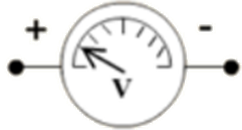
Voltmeter | It's a device that measures the difference in potential between two locations in an electric circuit. | (Image will be uploaded soon) |
Ammeter | It's a tool for determining the current in an electric circuit. | (Image will be uploaded soon) |
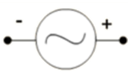
Alternating current | Alternating current is a type of current that changes direction fast on its own. | (Image will be uploaded soon) |
(Image will be uploaded soon)
A circuit diagram is a diagram that displays how different components in a circuit have been connected using traditional component symbols.
Electrical Potential
Electric potential is the work done in carrying a unit positive charge from infinity to a point.
If \[\text{W}\] is the work done \[\text{q}\] is the charge, then electric potential
\[\text{V = }\dfrac{\text{W}}{\text{q}}\]
The \[\text{SI}\] unit of electric potential is Volts \[\left( \text{V} \right)\]
Electric Potential Difference
The work done required to move a unit charge from one location to the other is defined as the electric potential difference between two points in an electric circuit carrying some current.
\[\text{Potential difference }\left( \text{V} \right)\text{ between two points = }\dfrac{\text{Work done }\left( \text{W} \right)}{\text{Charge }\left( \text{Q} \right)}\]
The electric potential difference between points \[\text{A}\] and \[\text{B}\]is,
\[{{\text{V}}_{\text{AB}}}\text{ = }\dfrac{\text{Work done to carry charge q from A to B}}{\text{Charge }\left( \text{Q} \right)}\]
The \[\text{SI}\] unit of electric potential difference is Volts \[\left( \text{V} \right)\] .
Example:
How much work is done in moving a charge of \[\text{4 C}\] across two points
having a potential difference \[\text{24 V}\] ?
Ans:
Given data is,
Charge, \[\text{Q = 4 C}\]
Potential difference, \[\text{V = 24 V}\]
Therefore, the amount of work \[\text{W}\] done in moving the charge can be calculated as,
\[\text{W = V }\!\!\times\!\!\text{ Q}\]
\[\text{W = 24}\times \text{4}\]
\[\text{W = 96 J}\]
Electric Potential Energy
The work done required to transport charges to their proper places against the electric field using a source of energy is known as electric potential energy.
The potential energy of the charges is used to store the work done.
Ohm’s Law
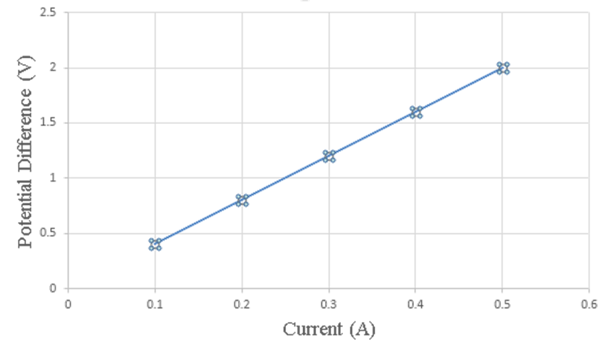
Under similar physical conditions, the current flowing through a wire is directly proportional to the difference in potential applied across its ends.
\[\text{V }\alpha \text{ I}\]
\[\dfrac{\text{V}}{\text{I}}\text{ = Constant}\]
\[\dfrac{\text{V}}{\text{I}}\text{ = R}\]
Therefore,
\[\text{V = IR}\]
Where \[\text{R}\] is the resistance offered.
(Image will be uploaded soon)
Resistance
Resistance is the opposition to the flow of current.
The \[\text{SI}\] unit of resistance is Ohm \[\left( \Omega \right)\].
\[\text{1 Ohm}\]is the resistance offered by a wire carrying \[\text{1 A}\]current when \[\text{1 V}\] is applied across its ends.
\[\text{ R = }\dfrac{\text{V}}{\text{I}}\]
\[\text{1 Ohm = }\dfrac{\text{1 Volt}}{\text{1 Ampere}}\]
Variable resistance is a component that regulates current without changing the voltage source.
A rheostat is a device that is commonly used to adjust the resistance in an electric circuit.
Factors Affecting Resistance
A conducting wire's resistance is determined by:
Nature of the material of the wire \[\left[ \text{Resistivity ( }\!\!\Omega\!\!\text{ )} \right]\]
Length of the wire \[\left( \text{l} \right)\]
Cross-sectional area of the wire \[\left( \text{A} \right)\]
Resistance is directly proportional to its length \[\left( \text{l} \right)\] and inversely proportional to the area of cross-section \[\left( \text{A} \right)\].
That is,
\[\text{R }\!\!\alpha\!\!\text{ l }\]
\[\text{R }\!\!\alpha\!\!\text{ }\dfrac{1}{\text{A}}\text{ }\]
Therefore,
\[\text{R }\!\!\alpha\!\!\text{ }\dfrac{\text{l}}{\text{A}}\text{ }\]
\[\text{R = }\rho \dfrac{\text{l}}{\text{A}}\]
Where,
\[\text{ }\!\!\rho\!\!\text{ }\left( \text{rho} \right)\] is a proportionality constant that refers to the electrical resistivity of the conductor's substance.
Resistivity
The resistance offered by a wire of unit length and unit cross-sectional area is called resistivity.
Resistivity is also known as specific resistance.
\[\Omega \text{m}\] ohm-meter is the \[\text{SI}\] unit for resistivity.
Metals and alloys have very low resistivity which in the range of \[{{10}^{-8}}\Omega \text{m to }{{10}^{-6}}\Omega \text{m}\] .
The resistivity of insulators such as rubber and glass is on the order of \[{{10}^{12}}\Omega \text{m to }{{10}^{17}}\Omega \text{m}\].
Temperature affects both a material's resistance and its resistivity.
An alloy's resistivity is usually higher than that of its constituent metals.
At high temperatures, alloys do not easily oxidise (burn) and hence, they're frequently used in electrical heating devices like electric irons and toasters.
Tungsten is nearly exclusively utilised in electric bulb filaments, while copper and aluminium are commonly used in electrical transmission lines.
Reciprocal of resistivity is called conductivity.
Conductivity can be calculated as;
\[\mho \text{ = }\dfrac{\text{l}}{\text{ }\!\!\Omega\!\!\text{ }}\]
\[\text{SI}\] unit of conductivity is \[\text{oh}{{\text{m}}^{\text{-1}}}{{\text{m}}^{\text{-1}}}\] or \[\text{mho-}{{\text{m}}^{\text{-1}}}\]
Effect of Temperature
A conductor's resistance increases linearly as the temperature rises.
As the temperature rises, an insulator's resistance rises as well.
As a semiconductor's temperature rises, its resistivity falls.
The resistivity of an alloy increases as the temperature rises.
Semiconductors and Superconductors
Semiconductors are materials with resistivity that fall between those of an insulator and a conductor.
Materials which lose their resistivity at low temperatures are called super conductors.
Examples:
The potential difference between the terminals of an electric heater is \[\text{45 V}\] when it draws a current of \[\text{3 A}\] from the source. What current will the heater draw if the potential difference is increased to \[\text{120 V}\] ?
Ans:
Given data is,
Potential difference \[\text{V = 45 V}\]and current \[\text{I = 3 A}\]
According to Ohm’s law,
\[\text{R = }\dfrac{\text{V}}{\text{I}}\]
\[\text{R = }\dfrac{45}{3}\]
\[\text{R = 15 }\Omega \]
When the potential difference is increased to \[\text{120 V}\]the current is
given by
\[\text{I = }\dfrac{\text{V}}{\text{R}}\]
\[\text{I = }\dfrac{120}{15}\]
\[\text{I = 8 A}\]
As a result, the heater's current becomes \[\text{8 A}\].
A wire of given material having length \[\text{l}\] and area of cross-section \[\text{A}\]has a resistance of \[\text{8 }\Omega \] . What would be the resistance of another wire of the same material having length \[\dfrac{\text{l}}{4}\] and area of cross-section \[\text{2A}\]?
Ans:
For first wire, resistance is;
\[{{\text{R}}_{1}}\text{ = }\!\!\rho\!\!\text{ }\dfrac{\text{l}}{\text{A}}\text{ = 8 }\!\!\Omega\!\!\text{ }\]
Now, for the second wire, resistance is
\[{{\text{R}}_{2}}\text{ = }\!\!\rho\!\!\text{ }\dfrac{\dfrac{\text{l}}{4}}{\text{2A}}\]
\[{{\text{R}}_{\text{2}}}=\rho \dfrac{\dfrac{1}{4}}{2\text{A}}\]
Since, \[\text{l = }\dfrac{\text{l}}{4}\]
Therefore,
\[{{\text{R}}_{2}}\text{ = }\!\!\rho\!\!\text{ }\dfrac{\text{l}}{\text{8A}}\]
\[{{\text{R}}_{\text{2}}}\text{ = }\dfrac{\text{l}}{\text{8}}{{\text{R}}_{\text{1}}}\]
Since, \[{{\text{R}}_{1}}=8\Omega \]
Therefore, \[{{\text{R}}_{\text{2}}}\] becomes
\[{{\text{R}}_{\text{2}}}\text{ = }\dfrac{\text{l}}{\text{8}}\times \text{8}\]
\[{{\text{R}}_{2}}=1\Omega \]
As a result, the new wire's resistance is \[\text{1}\Omega \]
Resistances in Series
The sum of the individual resistances of multiple resistors in series equals their equivalent resistance.
If resistances \[{{\text{R}}_{\text{1}}}\text{, }{{\text{R}}_{\text{2}}}\] and \[{{\text{R}}_{3}}\] are connected in series, then the equivalent resistance can be calculated as,
\[{{\text{R}}_{\text{s}}}\text{ = }{{\text{R}}_{1}}+{{\text{R}}_{2}}+{{\text{R}}_{3}}\]
When numerous resistors are connected in series, the combined resistance \[{{\text{R}}_{\text{s}}}\]equals the total of their individual resistances \[{{\text{R}}_{\text{1}}}\text{, }{{\text{R}}_{\text{2}}},{{\text{R}}_{3}}\] and hence, \[{{\text{R}}_{\text{s}}}\]is greater than any individual resistance.
In series circuit, current remains the same and potential difference vary.
(Image will be uploaded soon)
The current in a series circuit is constant throughout the electric circuit. As a result, connecting an electric lamp and an electric heater in series is clearly impractical, as they require currents of vastly different values to function effectively.
The main disadvantage of a series circuit is that if one component fails, the circuit is broken and none of the other components works.
Example:
An electric lamp, whose resistance is \[\text{25 }\Omega \] , and a conductor of \[\text{5 }\Omega \]
resistance are connected to a \[\text{9 V}\] battery as shown in below figure. Calculate
The total resistance of the circuit,
The current through the circuit.
(Image will be uploaded soon)
Ans:
The resistance of electric lamp,
\[{{\text{R}}_{\text{1}}}\text{ = 25 }\Omega \]
The resistance is connected in series,
\[{{\text{R}}_{2}}\text{ = 5 }\Omega \]
Then the total resistance in the circuit can be calculated as,
\[{{\text{R}}_{\text{s}}}\text{ = }{{\text{R}}_{1}}+{{\text{R}}_{2}}\]
\[{{\text{R}}_{\text{s}}}\text{ = 25}+5\]
\[{{\text{R}}_{\text{s}}}\text{ = 30 }\Omega \]
The overall difference in potential across the battery is
\[\text{V = 9 V}\]
According to Ohm’s law, the current through the circuit can be calculated as;
\[\text{I = }\dfrac{\text{V}}{{{\text{R}}_{\text{s}}}}\]
\[\text{I = }\dfrac{\text{9}}{\text{30}}\]
\[\text{I = 0}\text{.3 A}\]
Resistances in Parallel
If resistances \[{{\text{R}}_{\text{1}}}\text{, }{{\text{R}}_{\text{2}}}\] and \[{{\text{R}}_{3}}\] are connected in parallel, then the equivalent resistance \[{{\text{R}}_{\text{p}}}\] is given by
\[\dfrac{\text{1}}{{{\text{R}}_{\text{p}}}}\text{ = }\dfrac{\text{1}}{{{\text{R}}_{\text{1}}}}\text{+}\dfrac{\text{1}}{{{\text{R}}_{2}}}\text{+}\dfrac{\text{1}}{{{\text{R}}_{3}}}\]
The sum of the reciprocals of the individual resistances is equal to the reciprocal of the equivalent resistance of a group of resistances linked in parallel.
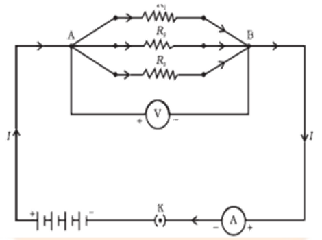
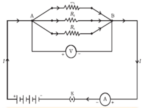
In parallel circuit, potential difference remains the same and current will be vary.
The current flowing through the electrical devices is divided in a parallel circuit.
This is especially useful when each device has a different resistance and requires a varied amount of current to function properly.
(Image will be uploaded soon)
Example:
In the circuit diagram given in below figure, suppose the resistors \[{{\text{R}}_{\text{1}}}\text{, }{{\text{R}}_{\text{2}}}\] and \[{{\text{R}}_{3}}\] have the values \[2\Omega ,4\Omega ,6\Omega \] respectively, which have been connected to a battery of \[\text{9 V}\].
Calculate
The current through each resistor,
The total current in the circuit, and
The total circuit resistance.
(Image will be uploaded soon)
Ans:
Given that
\[{{\text{R}}_{1}}\text{ = 2 }\Omega \]
\[{{\text{R}}_{2}}\text{ = 4 }\Omega \]
\[{{\text{R}}_{3}}\text{ = 6 }\Omega \]
The total potential difference across the battery is
\[\text{V = 9 V}\]
According to Ohm’s law,
The current \[{{\text{I}}_{1}}\], through \[{{\text{R}}_{\text{1}}}\] \[\text{= }\dfrac{\text{V}}{{{\text{R}}_{\text{1}}}}\]
\[{{\text{I}}_{1}}\text{ = }\dfrac{\text{V}}{{{\text{R}}_{\text{1}}}}\]
\[{{\text{I}}_{1}}\text{ = }\dfrac{9}{2}\text{ A}\]
\[{{\text{I}}_{1}}\text{ = 4}\text{.5 A}\]
The current \[{{\text{I}}_{2}}\], through \[{{\text{R}}_{2}}\] \[\text{= }\dfrac{\text{V}}{{{\text{R}}_{2}}}\]
\[{{\text{I}}_{2}}\text{ = }\dfrac{\text{V}}{{{\text{R}}_{2}}}\]
\[{{\text{I}}_{2}}\text{ = }\dfrac{9}{4}\text{ A}\]
\[{{\text{I}}_{2}}\text{ = }2.25\text{ A}\]
The current \[{{\text{I}}_{3}}\], through \[{{\text{R}}_{3}}\] \[\text{= }\dfrac{\text{V}}{{{\text{R}}_{3}}}\]
\[{{\text{I}}_{3}}\text{ = }\dfrac{\text{V}}{{{\text{R}}_{3}}}\]
\[{{\text{I}}_{3}}\text{ = }\dfrac{9}{6}\text{ A}\]
\[{{\text{I}}_{3}}\text{ = 1}\text{.5 A}\]
Therefore, the total current in the circuit can be calculated as;
\[\text{I = }{{\text{I}}_{1}}+{{\text{I}}_{2}}+{{\text{I}}_{3}}\]
\[\text{I = }4.5+2.25+1.5\]
\[\text{I = 8}\text{.25 A}\]
The total resistance \[{{\text{R}}_{\text{p}}}\] can be calculated as;
\[\dfrac{\text{1}}{{{\text{R}}_{\text{p}}}}\text{ = }\dfrac{\text{1}}{{{\text{R}}_{\text{1}}}}\text{+}\dfrac{\text{1}}{{{\text{R}}_{2}}}\text{+}\dfrac{\text{1}}{{{\text{R}}_{3}}}\]
\[\dfrac{\text{1}}{{{\text{R}}_{\text{p}}}}\text{ = }\dfrac{\text{1}}{\text{2}}\text{+}\dfrac{\text{1}}{4}\text{+}\dfrac{\text{1}}{6}\]
\[\dfrac{\text{1}}{{{\text{R}}_{\text{p}}}}\text{ = }\dfrac{\text{11}}{\text{12}}\]
Therefore,
\[{{\text{R}}_{\text{p}}}\text{ = }\dfrac{\text{12}}{\text{11}}\text{ }\!\!\Omega\!\!\text{ }\]
Heating Effect of Electric Current
The source energy is constantly dissipated fully in the form of heat if the electric circuit is purely resistive, that is, a configuration of resistors exclusively connected to a battery, this effect is called as the heating effect of electric current.
Electric heaters, electric irons, and other gadgets are operating on this effect.
For a steady current \[\text{I}\] , the amount of heat \[\text{H}\] produced in time \[\text{t}\] can be calculated as;
\[\text{H = VIt}\]
Joule’s Law of Heating:
When a current \[\text{I}\]flows through a resistor \[\text{R}\]heat is produced and this phenomena is called as Joule’s law of heating.
\[\text{H = }{{\text{I}}^{\text{2}}}\text{Rt}\]
Example:
\[\text{120 J}\] of heat is produced each second in a \[\text{6 }\Omega \] resistance. Find the
potential difference across the resistor.
Solution:
Given data is
\[\text{H = 120 J}\]
\[\text{R = 6 }\Omega \]
\[\text{t = 1 sec}\]
According to Joule’s Law of Heating effect,
\[\text{H = }{{\text{I}}^{\text{2}}}\text{Rt}\]
Therefore,
\[\text{I = }\sqrt{\dfrac{\text{H}}{\text{Rt}}}\]
\[\text{I = }\sqrt{\dfrac{120}{6\times 1}}\]
\[\text{I = }\sqrt{20}\]
\[\text{I = 4}\text{.47 A}\]
Thus the potential difference across the resistor \[\text{V}\]can be calculated as;
\[\text{V = IR}\]
\[\text{V = 4}\text{.47}\times \text{6}\]
\[\text{V = 26}\text{.82 V}\]
Applications of Heating Effect of Electric Current
Heat creation in a conductor is an unavoidable result of electric current.
Heat is undesirable because it converts useful electrical energy into heat.
The electric laundry iron, electric toaster, electric oven, electric kettle, and electric heater are all examples which are working on Joule’s heating effect.
As in an electric bulb, electric heating is also employed to produce light.
Bulb filaments are made of tungsten, a strong metal with a high melting point.
The fuse used in electric circuits is another prominent application of Joule's heating.
Fuse Wire:
A fuse wire is a wire that melts, breaks the circuit, and protects various appliances in household connections from damage.
It protects circuits and appliances by interrupting any too high electric current flow.
The fuse is connected to the device in series.
It consists of a piece of wire made of a metal or an alloy with the proper melting point, as well as a piece of wire made of a metal or an alloy with the appropriate melting point.
Aluminium, copper, iron, and lead alloys are used to make fuse wires.
The maximum safe current that can pass through the fuse wire increases as the thickness of the wire increases.
Electrical Energy
Because of the existence of resistance to the flow of current work has to be done in order to maintain the flow of current.
Since the potential difference \[\text{V}\] is the work done to carry unit positive charge from infinity to a point, the work done to carry a charge \[\text{q}\] is given by:
\[\text{W = qV}\]
But \[\text{I = }\dfrac{\text{q}}{\text{t}}\]
Therefore,
\[\text{W = ItV}\]
Since \[\text{V=IR}\]
Therefore,
\[\text{W = }{{\text{I}}^{\text{2}}}\text{Rt}\]
\[\text{W = }\dfrac{{{\text{V}}^{\text{2}}}\text{t}}{\text{R}}\]
This work done is stored as energy.
\[\text{SI}\] unit of electrical energy is Joule.
Electric Power
The rate at which electric energy is consumed is called electric power.
\[\text{Power }\!\!~\!\!\text{ = }\dfrac{\text{Work done}}{\text{Time}}\]
\[\text{P = }\dfrac{\text{W}}{\text{t}}\]
\[\text{P = V }\!\!\times\!\!\text{ }{{\text{I}}^{\text{2}}}\text{R}\]
\[\text{P = }{{\text{V}}^{\text{2}}}\text{R}\]
\[\text{P = VI}\]
\[\text{SI}\] unit of electric power is Watt.
Example:
An electric bulb is connected to a \[\text{230 V}\] generator. The current is \[\text{0}\text{.75 A}\]. What is the power of the bulb?
Solution:
We have
\[\text{V = 230 V}\]
\[\text{I = 0}\text{.75 A}\]
Thus, Power can be calculated as;
\[\text{P = VI}\]
\[\text{P = 230}\times 0.75\]
Therefore,
\[\text{P = 172}\text{.5 W}\]
Calculation of Power for House Hold Electricity
The commercial unit for electrical energy is the kilowatt hour\[\left( \text{kWh} \right)\]
\[\text{1kWh = 3,600,000 J}\]
\[\text{1kWh}=\text{3}\text{.6}\times \text{1}{{\text{0}}^{\text{6}}}\text{ J}\]
No. of units of electricity consumed in a household can be calculated as;\[\text{No}\text{. of units of electricity consumed in a household = }\!\!~\!\!\text{ No}\text{. of kWh}\]
\[\text{Total cost of electricity }\!\!~\!\!\text{ = Total units }\!\!\times\!\!\text{ Cost per unit of electricity}\]
Class 10 Science Chapter 11 Notes
What do you Mean by the Atomic Structure?
There are two points mentioned below that can surely clarify your concept regarding the atomic structure.
An atom comprises a nucleus that is positively charged and electrons that are negatively charged. These electrons revolve around the nucleus.
The valence electrons can constitute an electric current. In metal, these valence electrons can roam freely.
Definition of Charge
The charge is a fundamental property of matter. Due to the charge, a subject can exert electromagnetic force.
(Image will be uploaded soon)
Usage of Conductors and Insulators
Conductors can be defined as materials that offer least or no resistance to the flow of current whereas in insulators a greater resistance is offered against the flow of current.
Definition of Electric Potential and Potential Difference
Electric potential is the work done at a point to bring a unit positive charge from infinity to that point. The difference in electric potential between two different points is called the potential difference.
Notes of Chapter 11 Electricity Class 10
Electric Current Models
Electric current can be defined as the flow of charge from one point to another.
The expression for the electric current can be written as: I = q / t
Model of Electron Sea
Because of the passage of the ‘sea’ of free electrons, the electric current is possible to travel through a solid conductor. These sea of electrons are free to jump onto any neighboring atom.
(Image will be uploaded soon)
Electron’s Drift Velocity
As a result of potential differences, electric fields are generated inside the conductor. This results in the drift velocity of the electrons to attain maximum movement inside a metallic conductor.
(Image will be uploaded soon)
Working of Battery
The battery is working on a principle of potential difference which is generated inside it due to internal chemical reactions. Multiple cells connected together form a battery.
The following chemical reactions take place in a battery.
At anode
Cu(s) ⇌ Cu2+ (aq) + 2e−
At cathode
Ag(aq) + 2e− ⇌ 2Ag (s).
CBSE Class 10 Science Notes Chapter 11 Electricity
What is an Electric Circuit?
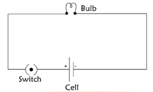
A current that travels in a closed-loop path is known as an electric circuit. Circuit diagrams are used to represent an electric circuit by using symbols for each component of the circuit. The diagram of an electric circuit is given below.
(Image will be uploaded soon)
Define Ohm’s Law
In an ohmic conductor, the passage of current is directly proportional to the applied potential difference between the two ends of the conductor.
(Image will be uploaded soon)
How to Define Resistance?
When the flow of current in an electric circuit is offered opposition, that opposition is known as resistance.
The resistance of a material depends on the following factors.
Resistance is inversely proportional to the cross-sectional area of the conductor.
Resistance is directly proportional to the length of the conductor.
Resistance is directly proportional to the nature of the conductor.
Resistance is directly proportional to the temperature of the conductor.
What is Resistivity?
Resistivity is the electrical resistance that is offered by a substance of unit length and unit cross-sectional area.
Related Study Materials for Class 10 Science Chapter 11 Electricity
Students can also download additional study materials provided by Vedantu for Science Class 10, Chapter 11–
S. No | Study Material Links for Electricity Class 10 |
1. | |
2. | |
3. | |
4. |
Chapter-wise Links for Science Class 10 Notes
S. No | CBSE Class 10 Revision Notes Links |
1 | |
2 | |
3 | |
4 | |
5 | |
6 | |
7 | |
8 | |
9 | |
10 | |
11 | |
12 |
Important Study Materials for Class 10 Science
S. No | Important Links for Science Class 10 |
1. | |
2. | |
3. | |
4. | |
5. |
Why Choose Vedantu for CBSE Class 10 Physics Notes?
Vedantu has some noticeable features which can lure the attention of the students to avail of its education program. Vedantu works for the excellence of education. The subject of Physics notes is very hopeful and supportive of the students.
Here are some opinions that can hearten you to join the Vedantu learning program.
Physics notes are meticulously arranged by highly skilled faculties for ease of comprehension.
The language used in the notes is familiar and comfortable for scholars to interpret effectively.
The notes are structured in a defined mode to ensure the inclusion of all significant illustrations without any ambiguity.
Content in the Physics notes encompasses important ideas, equations, proofs, and formulas in line with the CBSE syllabus.
These notes are a valuable resource for upcoming exams, offering central concepts that contribute to a solid foundation for achieving good marks.
Conclusion
For an enhanced comprehension of this subject, NCERT - Class 10 Science Chapter 11 - Electricity thoughtfully prepared by experienced educators at Vedantu is your invaluable companion. These notes break down the complexities of Electricity into easily digestible sections, helping you grasp new concepts, master formulas and navigate through questions effortlessly and quickly at the last minute as well. By immersing yourself in these notes, you not only prepare for your studies more efficiently but also develop a profound understanding of the subject matter.
FAQs on Electricity Class 10 Notes: CBSE Science Chapter 11
Q1. How can Anyone Make a Simple Circuit?
Ans: Students need to follow these given steps to construct a circuit.
One end of the wire should be connected to the light bulb holder.
In the negative end of the battery, connect the free-end wire.
The other end of the wire should be connected to the positive end of the battery.
Q2. What is the Heating Effect of Current?
Ans: As per Joule’s law, heat is directly proportional to the square of the current, directly proportional to the resistance of a given circuit, and heat is directly proportional to time for which current flows through the conductor.
Q3. What are the Types of Combinations of Resistors?
Ans: There are two types of combinations of resistors such as series and parallel.
In Series: The resistors carry the same current.
In Parallel: The resistors have the same potential difference.
Q4. Why Should you Choose Vedantu as your Learning Partner?
Ans: Vedantu has some significant features that are helpful for students. These features are as follows.
Time - saving learning skills.
Declaration about the decent result of a student.
Shape an assertive and robust concentration about the exam.
Enter anytime to our website and read from wherever you are either on your mobile or laptop.
Q5. What is electricity according to Class 10 Chapter 11 notes?
Electricity has been defined as the presence or rate of flow of electric charges in a conductor like copper wires. Thales, a well-known Greek Philosopher, observed the presence of an attractive capacity in certain materials when they were rubbed together. These two materials were later classified as positive and negative charges. Students can find a more detailed explanation in the Electricity Class 10 Notes Chapter 11 Science provided by Vedantu.
Q6. What is resistance according to Class 10 Science Chapter 11?
Resistance, as explained in Class 10 Science Chapter 11, is known as the opposition that is faced by the flow of current in an electric circuit. The amount of resistance depends on the following features of a particular material:
Resistance is directly proportional to the length, nature, and temperature of the conductor.
- Resistance and the conductor's cross-sectional area are inversely proportional to each other.
Q7. What are the topics covered in Class 10 Science Chapter 11 notes?
The Electricity Class 10 Notes Chapter 11 Science covers all the topics that are a part of the NCERT book and the latest syllabus provided by CBSE. These topics include:
Atomic Structure
Electric Charge
Usage of Conductors and Insulators
Definition of Electric Potential and Potential Difference
Electric Current Models
Model of Electron Sea
Electron’s Drift Velocity
Working of Battery
Electric Circuit
Ohm’s Law
Resistance and Resistivity
Q8. Define an electric circuit.
According to the CBSE Notes for Class 10 Science Chapter 10, a closed-loop path that has the presence of current traveling through it is called an electric circuit. The closed-loop provides the flowing current a return path, helping it go from one terminal of the power source to the other terminal. A full electric circuit can be represented with the help of circuit diagrams drawn using symbols for each component of the circuit.
Q9. Why should I refer to Vedantu CBSE Notes for Class 10 Science Chapter 11?
Physics in particular can be the branch of science that some students may find difficult to study. With the help of CBSE Notes for Class 10 Physics, understanding the concepts taught in Chapter 11 will become easier for students. Vedantu provides notes free of cost that have been prepared by expert and skilled professionals in an easy-to-understand language to help students get a strong grip over the subject and its different chapters in Class 10. These notes are 100% reliable and are based on the latest CBSE guidelines.