NCERT Exemplar for Class 12 Physics - Moving Charges And Magnetism - Free PDF Download
Free PDF download of NCERT Exemplar for Class 12 Physics Chapter 4 - Moving Charges And Magnetism solved by expert Physics teachers on Vedantu.com as per NCERT (CBSE) Book guidelines. All Chapter 4 - Moving Charges And Magnetism exercise questions with solutions to help you to revise complete syllabus and score more marks in your examinations.
To get more study material and information related to Physics Class 12 CBSE visit Vedantu.
Access NCERT Exemplar Solutions for CBSE Class 12 Science(Physics) Chapter 4 - Moving Charges and Magnetism
Exercise
MULTIPLE CHOICE QUESTIONS-I
4.1 Two charged particles traverse identical helical paths in a completely opposite sense in a uniform magnetic field $B={{B}_{0}}\overset{\wedge }{\mathop{k}}\,$.
(a) They have equal z-components of momenta.
(b) They must have equal charges.
(c) They necessarily represent a particle-antiparticle pair.
(d) The charge to mass ratio satisfy: ${{\left( \dfrac{e}{m} \right)}_{1}}+{{\left( \dfrac{e}{m} \right)}_{2}}=0$.
Ans: (d) The charge to mass ratio satisfy: ${{\left( \dfrac{e}{m} \right)}_{1}}+{{\left( \dfrac{e}{m} \right)}_{2}}=0$.
For a given pitch, $P=\dfrac{2\pi mv\cos \theta }{Bq}$ ,
$\dfrac{q}{m}=\dfrac{2\pi v\cos \theta }{BP}$ Where $\theta $ is the angle of velocity of charge particle with $x-axis$
If motion is not helical then $\theta =0$.
As the path of both the particles is identical and helical but of opposite direction in same magnetic field so, by the law of conservation of momenta.
${{\left( \dfrac{e}{m} \right)}_{1}}+{{\left( \dfrac{e}{m} \right)}_{2}}=0$
So, verifies Ans (d).
4.2 Biot-Savart law indicates that the moving electrons (velocity v) produce a magnetic field $B$ such that
(a) \[\mathbf{B}\bot \mathbf{v}\]
(b) \[\mathbf{B}||\mathbf{v}\]
(c) It obeys inverse cube law.
(d) It is along the line joining the electron and point of observation.
Ans: (a) \[\mathbf{B}\bot \mathbf{v}\]
By Biot-Savart law,
$dB=\dfrac{I\cdot dl\sin \theta }{{{r}^{2}}}$
Or $dB=\dfrac{I\times dl}{r}$
According to Biot-Savart law, if the magnetic field is not perpendicular to the motion of charge then it will not move in a helical path, which is not possible for motion of a charge in magnetic field.
So the magnetic field is perpendicular to the direction of flow of charge verifies Ans ‘a’.
4.3 A current carrying circular loop of radius $R$ is placed in the $x-y$ plane with center at the origin. Half of the loop with $x>0$ is now bent so that it now lies in the $y-z$ plane.
(a) The magnitude of magnetic moment now diminishes.
(b) The magnetic moment does not change.
(c) The magnitude of $B$ at$(0,0,z)$, \[z>>R\]increases.
(d) The magnitude of $B$ at$(0,0,z)$, \[z>>R\]is unchanged.
Ans: (a) the magnitude of magnetic moment now diminishes.
According to Fleming's left hand rule the direction of magnetic field due to a current- carrying circular loop is perpendicular to the plane of loop and unidirectional.
In first case, the direction of magnetic field is only in positive \[x-z\]direction but when it is bent then magnetic field due to first half loop is along \[-x\text{ axis}\](due to unfolded loop) and second half loop is along \[+x\text{ axis}\]direction. It is equal in magnitude so vector sum of equal and opposite magnetic field will cancel out each other.
Hence, this verifies Ans (a).
4.4 An electron is projected with uniform velocity along the axis of a current carrying long solenoid. Which of the following is true?
(a) The electron will be accelerated along the axis.
(b) The electron path will be circular about the axis.
(c) The electron will experience a force at 45° to the axis and hence execute a helical path.
(d) The electron will continue to move with uniform velocity along the axis of the solenoid.
Ans: (d) The electron will continue to move with uniform velocity along the axis of the solenoid.
The Lorentz force acts on a charged particle in a magnetic and electric field is
\[F=q\left( v\times B \right)\]
\[F=qvBsin\theta \]
As the charge is moving in the direction of electric field, $\theta =0$. The force due to the electric field will also be zero, so it will not affect the velocity of moving charge particle.
Hence this verifies Ans (d).
4.5 In a cyclotron, a charged particle
(a) Undergoes acceleration all the time.
(b) Speeds up between the dees because of the magnetic field.
(c) Speeds up in a dee.
(d) Slows down within a dee and speeds up between dees.
Ans: (b) Speeds up between the dees because of the magnetic field.
The electric field and magnetic field are perpendicular to each other. When a charge is placed between dees in empty space then it will experiences a force due to electric field and magnetic field which keeps it into a circular path.
Inside the dees, there is no electric field due to shielding effect of charge so the magnetic field is only responsible for the circular motion of charged particle. Inside dees the charge particle will moves with constant velocity.
So the charged particle accelerates inside dees and hence, this verifies Ans (b).
4.6 A circular current loop of magnetic moment M is in an arbitrary orientation in an external magnetic field B. The work done to rotate the loop by 30° about an axis perpendicular to its plane is
(a) MB.
(b) $\dfrac{\sqrt{3}}{2}MB$
(c) $\dfrac{MB}{2}$
(d) Zero.
Ans: (b) $\dfrac{\sqrt{3}}{2}MB$ and (d) Zero
When the axis of rotation of a loop is along$B$, then the angle between $\overrightarrow{B}$ and $\overrightarrow{A}$ is ${{90}^{\circ }}$always. So \[WD\]by loop to rotate i.e., \[WD=MB\text{ }cos~{{90}^{\circ }}\]which is zero.
This verifies the option (d).
But, when the axis of rotation of the loop is not along the direction of $B$, then the direction of vector $\overrightarrow{B}$ and $\overrightarrow{A}$ will change with time.
Work done by the loop during the orientation in uniform magnetic field is
$=MB\left( \cos {{\theta }_{2}}-\cos {{\theta }_{1}} \right)=MB\cos \theta $
$=MB\cos {{30}^{\circ }}=MB\dfrac{\sqrt{3}}{2}$
Hence, the Ans (b) is verified.
MULTIPLE CHOICE QUESTIONS-II MORE THAN ONE OPTION
4.7 The gyro-magnetic ratio of an electron in an H-atom, according to Bohr’s model, is
(a) Independent of which orbit it is in.
(b) Negative.
(c) Positive.
(d) Increases with the quantum number n.
Ans: (b) Negative
Angular momentum of electron is \[L=\dfrac{nh}{2\pi }\]
Magnetic moment of electron is \[M=n\left[ \dfrac{eh}{4\pi m} \right]\]
\[Gyromagnetic\text{ }ratio\text{ }=\dfrac{magnetic\text{ }moment}{angular\text{ }momentum}\]
\[Gyromagnetic\text{ }ratio=\dfrac{2\pi neh}{4\pi nhm}\]
\[Gyromagnetic\text{ }ratio=\dfrac{e}{2m}\]
\[Gyromagnetic\text{ }ratio=constant\]
It is independent of the orbit in which electron is revolving.
Since $e$is negative, the gyromagnetic ratio is negative.
Hence, this verifies the Ans is (b)
4.8 Consider a wire carrying a steady current $I$ placed in a uniform magnetic field $B$ perpendicular to its length. Consider the charges inside the wire. It is known that magnetic forces do no work. This implies that,
(a) Motion of charges inside the conductor is unaffected by $B$ since they do not absorb energy.
(b) Some charges inside the wire move to the surface as a result of$B$.
(c) If the wire moves under the influence of$B$, no work is done by the force.
(d) If the wire moves under the influence of$B$, no work is done by the magnetic force on the ions, assumed fixed within the wire.
Ans: (b) Some charges inside the wire move to the surface as a result of$B$ and (d) if the wire moves under the influence of$B$, no work is done by the magnetic force on the ions, assumed fixed within the wire.
Force $F$ on current-carrying conductor by magnetic field $B$ is given by the formula
\[F=BIL\sin \theta =I(B\times L)\]
Since the wire is placed perpendicular to the magnetic field $B$ , so the angle between normal to the wire and magnetic field is$0$.
$\operatorname{Sin}{{0}^{\circ }}=0$
So $F=0$
As there is no force on charges so their motion will remain unaffected.
This verifies the Ans (b).
So the work done by magnetic field is $W=F\cdot I\cos \theta $
$W=F\cdot I\cos {{90}^{\circ }}$which is equal to zero.
Hence, this verifies the Ans (d).
4.9 Two identical current carrying coaxial loops carry current $I$ in an opposite sense. A simple amperian loop passes through both of them once. Calling the loop as$C$,
(a) $\oint_{C}{B\cdot dl}=\mp 2{{\mu }_{0}}I$
(b) The value of $\oint_{C}{B\cdot dl}$is independent of sense of$C$.
(c) There may be a point on $C$ where $\overrightarrow{B}$and $\overrightarrow{dl}$ are perpendicular.
(d) $B$vanishes everywhere on$C$.
Ans: (b) the value of is independent of sense of$C$ and (c) There may be a point on $C$ where and are perpendicular.
Loops are identical and placed coaxially with carrying same current in opposite sense. So, inside the amperian loop of any type the direction of current will be opposite according to Ampere’s circuital law
$\oint_{C}{B\cdot dl}={{\mu }_{0}}(I-I)={{\mu }_{0}}(0)=0$
As the magnetic field inside (over everywhere) the loop is perpendicular to the direction of plane of loop, so
$\oint_{C}{B\cdot dl}=\left| B\cdot \overrightarrow{dl} \right|\cos {{90}^{\circ }}=0$
So, Ans (b) and (c) are verified.
4.10 A cubical region of space is filled with some uniform electric and magnetic fields. An electron enters the cube across one of its faces with velocity$v$, and a positron enters via opposite face with velocity$-v$. At this instant,
(a) The electric forces on both the particles cause identical accelerations.
(b) The magnetic forces on both the particles cause equal accelerations.
(c) Both particles gain or lose energy at the same rate.
(d) The motion of the center of mass ($CM$) is determined by ‘$B$’ alone.
Ans: (b) The magnetic forces on both the particles cause equal accelerations, (c) Both particles gain or lose energy at the same rate and (d) The motion of the center of mass ($CM$) is determined by ‘$B$’ alone.
As the $F=qE$ here $E$ is same but $q$is in opposite nature force. Electric force or acceleration is not identical. It discards Ans (a).
As the $F=q(v\times B)$ i.e. F is perpendicular to velocity and magnetic field, so particle revolves perpendicular to both and with uniform speed. But magnitude of acceleration by magnetic field is equal. It verifies Ans (b).
As magnitude of charge$\overrightarrow{v}$, $\overrightarrow{E}$and $B$ are constant, so gain or lose the energy at the same rate verifies Ans (c).
As there is no change in center of mass of particles therefore the motion of center of mass is determined by B alone. It verifies Ans (d).
4.11 A charged particle would continue to move with a constant velocity in a region wherein,
(a)\[E=0\], $B\ne 0$,
(b)$E\ne 0$,$B\ne 0$,
(c)$E\ne 0$,$B=0$,
(d)\[E=0\], $B=0$
Ans: (a)\[E=0\],$B\ne 0$, (b) $E\ne 0$,$B\ne 0$ and (d) \[E=0\], $B=0$
A changed particle will move with a constant velocity in a region if the force on it due to both the electric field and magnetic field is zero, or force on the charged particle due to electric field is equal and opposite to the force on it due to magnetic field.
i.e. \[Fe=qE\]and
\[Fm=q\left( v\times B \right)=qvBsin\theta \]
\[Fe=0\]if \[E=0\]and \[Fm=0\]if \[\theta =0\]or \[180\]
So, \[Fe=0\]if \[E=0\]and the particle is moving in the direction of magnetic field i.e. $B\ne 0$or\[E=0\];$B=0$
The resultant force −qE+q(v×B)=0
i.e. E≠0,b≠0
VERY SHORT ANSWER TYPE QUESTIONS
4.12 Verify that the cyclotron frequency $w=\dfrac{eB}{m}$has the correct dimensions of${{\left[ T \right]}^{-1}}$.
Ans: In cyclotron, charged particles are placed perpendicular to both $E$and$B$. Electric field exert force on particle resulting increase in velocity of particle and magnetic field keeps it into circular path. So it provides the centripetal force for revolution. So, \[\dfrac{m{{v}^{2}}}{R}=qv\times B\].
Here, $\theta =0$ as $\theta $ is angle between \[\overrightarrow{v}\]and $\overrightarrow{B}$
$\therefore \dfrac{m{{v}^{2}}}{R}=qvB\Rightarrow \dfrac{{{v}^{2}}}{Rv}=\dfrac{qB}{m}$ or $\dfrac{qB}{m}=\dfrac{v}{R}$
$\because w=\dfrac{qB}{m}$ so dimensions of below must be equal.
So $\left[ \omega \right]=\left[ \dfrac{qB}{m} \right]=\left[ \dfrac{v}{R} \right]$
$\left[ \dfrac{2\pi }{T} \right]=\left[ \dfrac{L{{T}^{-1}}}{L} \right]=\left[ {{T}^{-1}} \right]$
So dimensions of $\omega $ is ${{\left[ T \right]}^{-1}}$.
4.13 Show that a force that does no work must be a velocity dependent force.
Ans: The work done by a force is given by\[dW=F\cdot dl=Fdl\cos \theta \].
As work done by force is zero, so
\[dW=F.dl=0\]
$\Rightarrow F\cdot \dfrac{dl}{dt}\times dt=0$
\[dW=F\cdot vdt=0\]
as $dt\ne 0\left[ \therefore F\cdot v=0 \right]$
So $F$must be velocity-dependent, i.e. angle between $F$ and $v$ must be always, then
For $F\cdot v=0$
\[Fvcos\theta =cos{{90}^{\circ }}\]
$\theta ={{90}^{\circ }}$
If $v$ changes direction then to make $\theta ={{90}^{\circ }}$, $F$must change angle according to $v$. So $F$ is dependent of v to make work done zero.
4.14 The magnetic force depends on velocity vector which depends on the inertial frame of reference. Does then the magnetic force differ from inertial frame to frame? Is it reasonable that the net acceleration has a different value in different frames of reference?
Ans: The magnetic force changes from inertial frame to frame, i.e. the magnetic force depends on frame of reference. So the net acceleration which comes into existence out of this is, however, frame independent (non-relativistic physics) for inertial frame.
4.15 Describe the motion of a charged particle in a cyclotron if the frequency of the radio frequency $\left( rf \right)$ field were doubled.
Ans: When the frequency ω of electric field (oscillator) is doubled, the time-period $\left[ T=\dfrac{2\pi }{\omega } \right]$becomes half. So the charged particle will take half time to reach between dees. Hence, a charged particle accelerates as it moves in circular path between the dees during motion in Dee’s the radius of moving charged particle remain same.
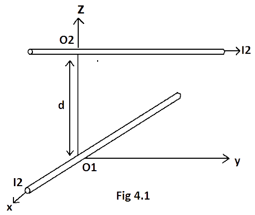
4.16 Two long wires carrying current I1 and I2 are arranged as shown in Fig. 4.1. The one carrying current I1 is along is the x-axis. The other carrying current I2 is along a line parallel to the y-axis given by x = 0 and z = d. Find the force exerted at O2 because of the wire along the x-axis.
Ans: We know that the force on current $\left( I \right)$ carrying conductor placed in magnetic field $B$is
\[F=I\left( L\times B \right)=ILBsin\theta \]
The direction of magnetic field at ${{O}_{2}}$ due to the current ${{I}_{1}}$ is parallel to the $Y-axis$ and in $-Y$ direction.
As wire of current ${{I}_{2}}$ is parallel to$Y-axis$, current in ${{I}_{2}}$ is also along$Y-axis$. So ${{I}_{2}}$ and ${{B}_{1}}$ (magnetic field due to current${{I}_{1}}$) are also along $Y-axis$ i.e. angle between ${{I}_{2}}$ and ${{B}_{1}}$ is zero. So magnetic force ${{F}_{2}}$ on wire of current ${{I}_{2}}$ is ${{F}_{2}}={{B}_{1}}{{I}_{2}}{{L}_{1}}\sin {{0}^{\circ }}=0$
Hence, force on ${{O}_{2}}$ due to wire of current ${{I}_{1}}$ is zero.
SHORT ANSWER TYPE QUESTIONS
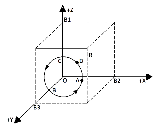
4.17 A current carrying loop consists of 3 identical quarter circles of radius$R$, lying in the positive quadrants of the$X-Y$, $Y-Z$ and $Z-X$ planes with their centers at the origin, joined together. Find the direction and magnitude of $B$ at the origin.
Ans: In the figure, consider the 3 quadrants of conductors$AB$,$BC$ and $CD$ along positive$X-Y$, $Y-Z$ and $Z-X$ planes respectively. $A$ and $D$ are connected to a battery which is responsible for the flow of current $I$ through the three quadrants of radius $R$ in the coordinate of $A$ or $D$ \[\left( R,0,0 \right)\], \[B\left( 0,\text{ }R,0 \right)\] and of \[C\left( 0,0,R \right)\]. Now the direction of magnetic field by right-hand thumb rule due to quadrants $AB$, $BC$ and $CD$ are $+{{B}_{1}}$ , ${{B}_{2}}$ and ${{B}_{3}}$ along $+Z$, $+X$ and $+Y$ directions respectively. So, at the center of quadrant
$\because \overrightarrow{B}=\dfrac{{{\mu }_{0}}I}{2\pi R}\cdot \dfrac{\dfrac{\pi }{2}}{2\pi }$
$B=\dfrac{{{\mu }_{0}}I}{8\pi R}$
So M.F. due to quadrants$AB$, $BC$and $CD$ at their center $O$ are${{B}_{1}}$ , ${{B}_{2}}$ and ${{B}_{3}}$ respectively.
${{B}_{1}}=\dfrac{{{\mu }_{0}}I}{8\pi R}\widehat{k}$, \[{{B}_{2}}=\dfrac{{{\mu }_{0}}I}{8\pi R}\widehat{i}\] and${{B}_{3}}=\dfrac{{{\mu }_{0}}I}{8\pi R}\widehat{j}$.
So net magnetic field at origin due to three current carrying loops are \[B={{B}_{1}}+{{B}_{2}}+{{B}_{3}}\].
$B=\dfrac{{{\mu }_{0}}I}{8\pi R}\left[ \widehat{i}+\widehat{j}+\widehat{k} \right]$
The resultant of${{B}_{1}}$, ${{B}_{2}}$ and ${{B}_{3}}$ will be diagonal $OR$ of cube of side${{B}_{1}}$ , ${{B}_{2}}$ , ${{B}_{3}}$ as the $\left| {{B}_{1}} \right|=\left| {{B}_{2}} \right|=\left| {{B}_{3}} \right|$.
4.18. A charged particle of charge e and mass m is moving in an electric field $\overrightarrow{E}$and magnetic field$\overrightarrow{B}$ . Construct dimensionless quantities and quantities of dimension ${{\left[ T \right]}^{-1}}$.
Ans: When a charged particle is placed in an electric and magnetic field, it starts moving in a helical motion where electric field $E$ and $B$ is perpendicular to direction of motion and electric field exerts a force on charged particle and centripetal force is applied by magnetic force
\[{{F}_{m}}=qvBsin{{90}^{\circ }}=qvB\]...... (1)
We know that Centripetal force is$\dfrac{m{{v}^{2}}}{R}$ ....... (2)
By equation (1) and (2)
$\dfrac{m{{v}^{2}}}{R}=qvB$
$\dfrac{v}{R}=\dfrac{qB}{m}$
$\because v=\omega R$and \[q=e\]
Angular velocity
$\omega =\dfrac{v}{R}=\dfrac{eB}{m}$
Dimensional formula for angular velocity $\omega $
$\omega =\left[ \dfrac{eB}{m} \right]=\left[ \dfrac{v}{R} \right]=\left[ {{T}^{-1}} \right]$
4.19 An electron enters with a velocity $v={{v}_{0}}\widehat{i}$ into a cubical region (faces parallel to coordinate planes) in which there are uniform electric and magnetic fields. The orbit of the electron is found to spiral down inside the cube in plane parallel to the $X-Y$ plane. Suggest a configuration of fields $\overrightarrow{E}$and $\overrightarrow{B}$ that can lead to it.
Ans: The velocity of electron is$v={{v}_{0}}\widehat{i}$, i.e. along \[X-axis\]as magnetic field is perpendicular to velocity so it is in $Y$direction.
The moving electron enters into cubical region. The force on electron due to Lorentz force
\[F=q\left( E+v\times B \right)\]
By putting the values
${{F}_{m}}=-e\left[ {{v}_{0}}\widehat{i}\times B\widehat{k} \right]=-e{{v}_{0}}B\widehat{j}$
Which revolve the electron in $X-Y$ plane.
The force due to electric field ${{F}_{e}}=e\overrightarrow{E}\widehat{K}$ accelerates the electron along \[z-axis\]and force due to magnetic field keeps it in circular motion, which in turn increases the radius of circular path. So the motion becomes helical path.
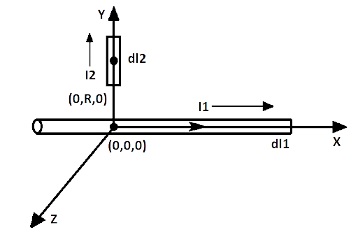
4.20 Do magnetic forces obey Newton’s third law? Verify for two current elements $d{{l}_{1}}=dl\widehat{i}$located at the origin and $d{{l}_{2}}=dl\widehat{j}$ located at\[(0,R,0)\]. Both carry current$I$.
Ans: Fig. shows two current elements $d{{l}_{1}}$ and $d{{l}_{2}}$ located at $(0,0,0)$ and \[(0,R,0)\].The direction of magnetic field on $d{{l}_{2}}$ due to magnetic field ${{B}_{1}}$ by $d{{l}_{1}}$ will be along \[+Z\] direction by Right Hand Grip Rule i.e. directions of ${{I}_{2}}$ and ${{B}_{1}}$ are perpendicular.
Force on $d{{l}_{2}}$due to $d{{l}_{1}}$
\[{{F}_{1}}={{B}_{1}}{{I}_{2}}d{{l}_{2}}sin{{90}^{\circ }}={{B}_{1}}{{I}_{2}}{{l}_{2}}\]
Similarly, angle between magnetic field ${{B}_{2}}$ and current ${{I}_{1}}$ is${{0}^{\circ }}$. So the force acting on $d{{l}_{1}}$ due to $d{{l}_{2}}$
\[{{F}_{2}}={{B}_{2}}{{I}_{1}}d{{l}_{1}}sin{{0}^{\circ }}=0\]
\[\therefore \left| d{{l}_{1}} \right|=\left| d{{l}_{2}} \right|=\left| dl \right|\]
So the magnetic force existing on $d{{l}_{1}}$is zero but on $d{{l}_{2}}$ due to $d{{l}_{1}}$ is not zero so magnetic forces do not obey Newton’s third law.
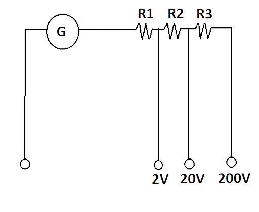
4.21 A multirange voltmeter can be constructed by using a galvanometer circuit, as shown in Fig. 4.2. We want to construct a voltmeter that can measure$2V$, $20V$ and $200V$ using a galvanometer of resistance $10\Omega $ and that produces maximum deflection for current of$1mA$. Find ${{R}_{1}}$, ${{R}_{2}}$and ${{R}_{3}}$that have to be used.
Ans: Given resistance of Galvanometer $({{R}_{g}})$is$10\Omega $.
Maximum current deflection $({{I}_{g}})$ is \[1mA=1\times {{10}^{-3}}A\]
For$2V$, ${{R}_{g}}$ and ${{R}_{1}}$ are connected in series:
\[{{I}_{g}}\left( {{R}_{g}}+{{R}_{1}} \right)=2V\]
\[1\times {{10}^{-3}}\left[ 10+{{R}_{1}}\text{ } \right]=2\]
\[{{R}_{1}}=2000-10=1990\Omega \]
For$20V$,${{R}_{g}}$, ${{R}_{1}}$ and ${{R}_{2}}$ are connected in series:
\[I\left( {{R}_{g}}+R \right)=V\text{ }\because \text{R=}{{\text{R}}_{1}}+{{R}_{2}}\]
\[{{I}_{g}}\left[ {{R}_{g}}+{{R}_{1}}+{{R}_{2\text{ }}} \right]=20V\]
\[{{10}^{-3}}\left[ 10+1990+{{R}_{2}} \right]=20\]
\[{{R}_{2}}=20000-2000\]
\[{{R}_{2}}=18000\Omega =18k\Omega \]
For\[200V\], ${{R}_{g}}$, ${{R}_{1}}$ , ${{R}_{2}}$ and ${{R}_{3}}$ are connected in series:
\[{{I}_{g}}\text{ }\left[ {{R}_{g}}+{{R}_{1}}+{{R}_{2}}+{{R}_{3}} \right]=200V\], as \[R=\left( {{R}_{1}}+{{R}_{2}} \right)+{{R}_{3}}\]
\[{{10}^{-3}}\left[ 10+1990+18000+{{R}_{3}} \right]=200\]
\[20000+{{R}_{3}}=200000\]
\[{{R}_{3\text{ }}}\text{= }20000020000\]
\[=180000\Omega =180k\Omega \]
Hence, \[{{R}_{1}}=1990\Omega \]; \[{{R}_{2}}=18k\Omega \]; \[{{R}_{3}}=180k\Omega \]
4.22 A long straight wire carrying current of 25A rests on a table as shown in Fig. 4.3. Another wire PQ of length 1m, mass 2.5 g carries the same current but in the opposite direction. The wire PQ is free to slide up and down. To what height will PQ rise?
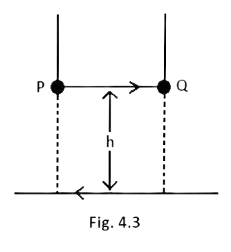
Ans: Given current in wire\[\left( {{l}_{2}} \right)=25\text{ }A\],
Length of wire\[PQ\left( {{L}_{2}} \right)=1\text{ }m\],
Mass of wire $PQ\left( m \right)=2.5g$
Wire $PQ$ must experience a repulsive force due to magnetic field by wire$AB$.
Let the wire is balanced at height h thus, magnetic force due to wire $AB$ on $PQ$ should be equal and opposite to weight pf the body\[\left( =mg \right)\].
\[{{F}_{m}}=mg\]....... (1)
Also the magnetic force due to a wire
${{F}_{m}}=ILB\sin \theta $ …………….. (2)
The angle between ${{B}_{1}}$ and $I$in $PQ$ is${{90}^{\circ }}$. So by equation (1) and (2) we get,
\[ILB=mg\text{ }\left( sin{{90}^{\circ }}=0 \right)\]
\[{{B}_{1\text{ }}}{{I}_{2}}{{L}_{2}}=mg\]
$\dfrac{{{\mu }_{0}}{{I}_{1}}}{2\pi h}{{I}_{2}}{{l}_{2}}\sin {{90}^{\circ }}=mg\text{ }\left[ {{I}_{1}}={{I}_{2}}=I=25A \right]$
$\dfrac{{{\mu }_{0}}{{I}^{2}}{{l}_{2}}}{2\pi h}=mg$
$h=\dfrac{{{\mu }_{0}}{{I}^{2}}{{l}_{2}}}{2\pi mg}=\dfrac{4\pi \times {{10}^{-7}}\times 25\times 25\times 1}{2\pi \times 2.5\times {{10}^{-3}}\times 9.8}$
$=\dfrac{2\times 625}{2.5\times 9.8}\times {{10}^{-7+3}}$
$=\dfrac{20\times 25}{9.8}\times {{10}^{-4}}$
$=51\times {{10}^{-4}}m$
$=51\times {{10}^{-2}}cm=0.51cm$
LONG ANSWER TYPE QUESTIONS
4.23 A $100$ turn rectangular coil \[ABCD\](in \[XY\]plane) is hung from one arm of a balance (Fig. 4.4). A mass \[500g\] is added to the other arm to balance the weight of the coil. A current \[4.9A\]passes through the coil and a constant magnetic field of $0.2T$acting inward (in $xz$plane) is switched on such that only arm $CD$ of length $1cm$ lies in the field. How much additional mass ‘$m$’ must be added to regain the balance?
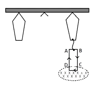
Fig. 4.4
Ans: The magnetic field is perpendicular to arms $BC$ and$AD$, so torque will act on $CD$ and $AB$ arms due to it, Coil rotate.
When current of \[4.9A\] does not pass through the coil the balance measures mass of coil \[500g\].
On arm $AD$ and $BC$of rectangular coil magnetic force due to M.F. will be equal and opposite so it will rotate the coil horizontally not vertically up or down. So does not affect the balance.
When current of \[4.9A\] passes through the coil, downward force acts on arm $CD$ due to magnetic field. Length of arm $CD$ is\[1cm\left( {{10}^{-2}}m \right)\].
Force acting on arm \[CD={{F}_{m}}=B\times I\cdot l=BIlsin\theta \] [ $\theta $ is angle between $B$ and $I$ in $CD$
\[=0.2\times 4.9\times sin{{90}^{\circ }}\times {{10}^{-2}}\]
Or \[{{F}_{m}}=0.98\text{ }\times {{10}^{-2}}N\]
Now let the weight mg is added on other side of beam balance to balance the coil
\[Mg={{F}_{m}}\]
\[m\times 9.8=0.98\times {{10}^{-2}}\]
$m=\dfrac{0.98}{9.8}\times {{10}^{-2}}={{10}^{-3}}kg=1g$
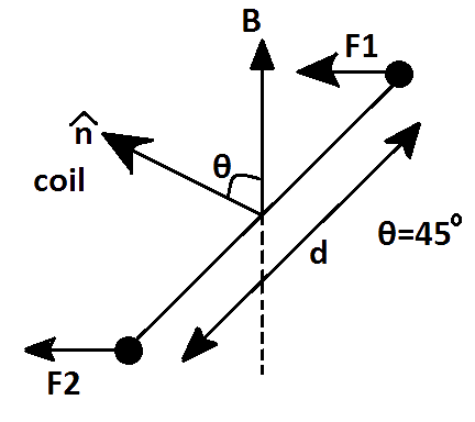
4.24 A rectangular conducting loop consists of two wires on two opposite sides of length ‘$l$’ joined together by rods of length ‘$d$’. The wires are each of the same material but with cross-sections differing by a factor of$2$. The thicker wire has a resistance $R$ and the rods are of low resistance, which in turn are connected to a constant voltage source${{V}_{0}}$. The loop is placed in uniform a magnetic field $B$ at ${{45}^{\circ }}$to its plane. Find$\left( \tau \right)$, the torque exerted by the magnetic field on the loop about an axis through the centers of rods.
Ans:
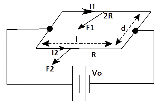
Force on axis $AB$ due to magnetic field is \[{{F}_{1}}={{I}_{1}}lB\]
$=\dfrac{{{V}_{0}}}{{{R}_{1}}}lB=\dfrac{{{V}_{0}}}{2R}lB$
It is acting perpendicular to the arm $AB$ towards observe.
Torque due to force ${{F}_{1}}$ about axis $EF$
${{\tau }_{1}}={{F}_{1}}\times \dfrac{d}{2}\sin {{45}^{\circ }}$
$\Rightarrow {{\tau }_{1}}=\dfrac{{{V}_{0}}}{2R}lB\times \dfrac{d}{2}\times \dfrac{1}{\sqrt{2}}$
$=\dfrac{{{V}_{0}}lBd}{4\sqrt{2}R}$
(In the anticlock wise direction)
Now the force on arm $DC$ due to magnetic field,
${{F}_{2}}={{I}_{2}}lB$
$\Rightarrow {{F}_{2}}=\dfrac{{{V}_{0}}}{{{R}_{2}}}lB$
$\Rightarrow {{F}_{2}}=\dfrac{{{V}_{0}}}{R}lB$
Torque due to force ${{F}_{2}}$ about axis $EF$ is
${{\tau }_{2}}={{F}_{2}}\times \dfrac{d}{2}\sin {{45}^{\circ }}$
${{\tau }_{2}}=\dfrac{{{V}_{0}}}{R}lB\times \dfrac{d}{2}\times \dfrac{1}{\sqrt{2}}$
${{\tau }_{2}}=\dfrac{{{V}_{0}}lBd}{2\sqrt{2}R}$
(In the clock wise direction)
Net Torque is \[\tau ={{\tau }_{2}}-{{\tau }_{1}}\]
$\Rightarrow \dfrac{{{V}_{0}}lBd}{2\sqrt{2}R}-\dfrac{{{V}_{0}}lBd}{4\sqrt{2}R}$
$\Rightarrow \dfrac{{{V}_{0}}lBd}{2\sqrt{2}R}\left( 1-\dfrac{1}{2} \right)$
$\Rightarrow \dfrac{{{V}_{0}}lBd}{4\sqrt{2}R}$
But, $l\times d=A$
So, $\tau =\dfrac{{{V}_{0}}lBd}{4\sqrt{2}R}$
4.25 An electron and a positron are released from \[\left( 0,0,0 \right)\]and $\left( 0,0,1.5R \right)$ respectively in a uniform magnetic field $B={{B}_{0}}\widehat{i}$, each with an equal momentum of magnitude $\overrightarrow{p}=e\overrightarrow{B}R$ . Under what conditions on the direction of momentum will the orbits be non-intersecting circles?
Ans: As $B={{B}_{0}}\widehat{i}$ so magnetic field is along$+X-axis$. The circular motion of the momenta of both an electron and a positron are in $Y-Z$ plane. Let ${{p}_{1}}$ and ${{p}_{2}}$ are the momentum of the electron and positron respectively, the magnitude of charge and momentum of both are equal so they revolve in $Y-Z$plane due to MF is$B={{B}_{0}}\widehat{i}$. But in opposite sense with same radius R as the direction, ${{p}_{1}}$ and ${{p}_{2}}$ are opposite.
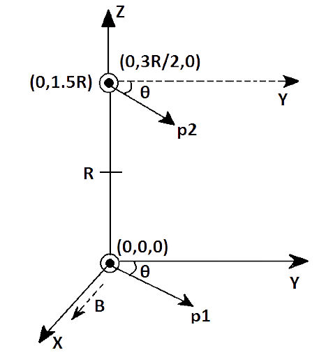
Let ${{p}_{1}}$ and ${{p}_{2}}$ make an angle \[+\theta \]and $-\theta $with $Y-axis$, as shown in the above figure. The centers of the respective circles must be perpendicular to the momentum and at a distance$R$. Let the Centre of revolving electron and positron are ${{C}_{e}}$ and ${{C}_{p}}$respectively so coordinates of ${{C}_{e}}$ will be \[\left( 0,+R\text{ }sin\theta .R\text{ }cos\theta \right)\]and that of ${{C}_{p}}$ will be \[\left( 0,-R\text{ }sin\theta ,\dfrac{3}{2}R-Rcos\theta \right)\]
The planes of circular paths are in $Y-Z$ plane.
The condition that the circular path of the electron and position are non-intersecting circles is that the distance ($d$) between their centers must be greater than $2R$
\[id>d>2R\]
\[{{d}^{2}}={{\left( {{x}_{2}}-{{x}_{1}} \right)}^{2}}+{{\left( {{y}_{2}}-{{y}_{1}} \right)}^{2}}+{{\left( {{z}_{2}}-{{z}_{1}} \right)}^{2}}\]
\[{{d}^{2}}={{\left( 0-0 \right)}^{2}}+{{\left( +R\sin \theta +R\sin \theta \right)}^{2}}+{{\left( R\cos \theta -\dfrac{3}{2}R+Rcos\theta \right)}^{2}}\]
\[{{d}^{2}}={{\left( 2R\sin \theta \right)}^{2}}+{{\left( 2R\cos \theta -\dfrac{3}{2}R \right)}^{2}}\]
\[{{d}^{2}}=4{{R}^{2}}{{\sin }^{2}}\theta +4{{R}^{2}}{{\cos }^{2}}\theta +\dfrac{9}{4}{{R}^{2}}-6{{R}^{2}}\cos \theta \]
\[{{d}^{2}}=4{{R}^{2}}+\dfrac{9}{4}{{R}^{2}}-6{{R}^{2}}\cos \theta \]... (I)
\[d>2R\]
\[{{d}^{2}}>4{{R}^{2}}\]
\[4{{R}^{2}}+\dfrac{9}{4}{{R}^{2}}-6{{R}^{2}}\cos \theta >4{{R}^{2}}\]
\[\dfrac{9}{4}{{R}^{2}}-6{{R}^{2}}\cos \theta >0\]
\[3{{R}^{2}}\left( \dfrac{3}{4}-2\cos \theta \right)>0\]
\[3{{R}^{2}}>0\]is rejected
$2\cos \theta <\dfrac{3}{4}$
$\cos \theta <\dfrac{3}{8}$ is the condition that two circular paths do not intersect; $\theta $ is angle of momentum of electron or positron with $Y-axis$.
4.26 A uniform conducting wire of length $12a$ and resistance $R$ is wound up as a current carrying coil in the shape of (i) an equilateral triangle of side $a$; (ii) a square of sides $a$ and, (iii) a regular hexagon of sides . The coil is connected to a voltage source ${{V}_{0}}$. Find the magnetic moment of the coils in each case.
Ans: (i) The coil of shape equilateral triangle is made up with side$a$. So the number of turns in coil $=\dfrac{12a}{3a}=4$turns.
$\therefore $Magnetic moment \[=nIA=4\times I\times \dfrac{\sqrt{3}}{4}{{a}^{2}}\]
Magnetic moment of the triangular oil$=\sqrt{3}I{{a}^{2}}$.
(ii) Number of turns in coil of square-shape of side $a=\dfrac{12a}{4a}=3$ turns. So magnetic moment due to square shaped coil $=nIA=3I\times {{a}^{2}}=3I{{a}^{2}}$
(iii) For a regular hexagon-shaped coil of side$a$, number of turns in coil
$=\dfrac{12a}{6a}=2$
$\therefore $Magnetic moment $=nIA=2I\cdot \left( \dfrac{\sqrt{3}}{4}{{a}^{2}} \right)\cdot 6=3\sqrt{3}I{{a}^{2}}$
4.27. Consider a circular current-carrying loop of radius $R$ in the $x-y$ plane with center at origin. Consider the line integral
$\Im \left( L \right)=\left| \int\limits_{-L}^{L}{B\cdot dl} \right|$ taken along$Z-axis$.
(a) Show that $\Im \left( L \right)$ monotonically increases with$L$.
(b) Use an appropriate Amperian loop to show that\[\Im \left( \infty \right)={{\mu }_{0}}I\], where $I$ is the current in the wire.
(c) Verify directly the above result.
(d) Suppose we replace the circular coil by a square coil of sides $R$ carrying the same current$I$. What can you say about $\Im \left( L \right)$ and $\Im \left( \infty \right)$ ?
Ans: (a) \[B\left( z \right)\]point in the same direction of \[Z-axis\]and hence $\Im \left( L \right)$ is monotonical function of $L$ as $B$ and $dl$ are along the same direction. So
$B\cdot dl=Bdl\cos \theta =Bdl\cos {{0}^{\circ }}=Bdl$
(b) $\Im \left( L \right)$+ Contribution from large distance on contour \[C={{\mu }_{0}}I\]
$\therefore As\text{ }L\to \infty $
Contribution from large distance $\to 0\text{ }\left( As\text{ }B\alpha \dfrac{1}{{{r}^{3}}} \right)$
$\therefore \Im \left( \infty \right)-{{\mu }_{0}}I$
(c) The magnetic field due to circular current-carrying loop of radius $R$ in $X-Y$ plane with center at origin at with center at origin at any point lying at distance a from origin. Consider a loop of current- carrying conductor placed in $X-Y$plane. A point $P$ is in $+Z$ direction at distance$z$, i.e. $OP=z$.
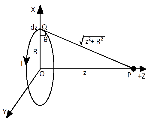
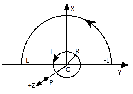
Again consider an element \[dz\]on loop of conductor as shown in figure below.
Let angle between $R$ and \[QP=\theta \]then magnetic field at $P$ due to loop is
$B\widehat{z}=\dfrac{{{\mu }_{0}}I{{R}^{2}}}{2{{\left( {{z}^{2}}+{{R}^{2}} \right)}^{\dfrac{3}{2}}}}$ Integrating both sides w.r.t. z and z can vary from -d to +d
\[\int\limits_{-\infty }^{\infty }{B\widehat{z}dz=}\int\limits_{-\infty }^{+\infty }{\dfrac{{{\mu }_{0}}I{{R}^{2}}dz}{2{{\left( {{z}^{2}}+{{R}^{2}} \right)}^{\dfrac{3}{2}}}}}\]
$\tan \theta =\dfrac{z}{R}$
\[z=Rtan\theta \]
Differentiating both sides:
\[dz=R\cdot se{{c}^{2}}\theta .d\theta \]
$\cos \theta =\dfrac{R}{\sqrt{{{z}^{2}}+{{R}^{2}}}}$
${{\cos }^{2}}\theta =\dfrac{R}{\sqrt{{{z}^{2}}+{{R}^{2}}}}$
\[\int\limits_{-\infty }^{\infty }{Bzdz=\dfrac{{{\mu }_{0}}I}{2}}\int\limits_{-\infty }^{+\infty }{\dfrac{{{R}^{2}}}{\left( {{z}^{2}}+{{R}^{2}} \right)}}\dfrac{dz}{\sqrt{{{z}^{2}}+{{R}^{2}}}}\]
\[\int\limits_{-\infty }^{\infty }{Bzdz=\dfrac{{{\mu }_{0}}I}{2}}\int\limits_{-\dfrac{\pi }{2}}^{+\dfrac{\pi }{2}}{{{\cos }^{2}}\theta \cdot \dfrac{R{{\sec }^{2}}\theta .d\theta }{\sqrt{{{z}^{2}}+{{R}^{2}}}}}\text{ }\left[ \because \cos \theta =\dfrac{R}{\sqrt{{{z}^{2}}+{{R}^{2}}}} \right]\]
\[\int\limits_{-\infty }^{\infty }{Bzdz=\dfrac{{{\mu }_{0}}I}{2}}\int\limits_{-\dfrac{\pi }{2}}^{+\dfrac{\pi }{2}}{\dfrac{Rd\theta }{\sqrt{{{z}^{2}}+{{R}^{2}}}}}\text{=}\dfrac{{{\mu }_{0}}I}{2}\int\limits_{-\dfrac{\pi }{2}}^{+\dfrac{\pi }{2}}{\cos \theta d\theta }\text{ }\]
\[\int\limits_{-\infty }^{\infty }{Bzdz=\dfrac{{{\mu }_{0}}I}{2}}\left[ \sin \theta \right]_{-\dfrac{\pi }{2}}^{\dfrac{\pi }{2}}\text{=}\dfrac{{{\mu }_{0}}I}{2}\left[ \sin \dfrac{\pi }{2}-\sin \dfrac{-\pi }{2} \right]\text{ }\]
\[\int\limits_{-\infty }^{\infty }{Bzdz=\dfrac{{{\mu }_{0}}I}{2}}\left[ 1+1 \right]\text{=}{{\mu }_{0}}I=\int\limits_{-\infty }^{+\infty }{B\widehat{z}dz}={{\mu }_{0}}I\]
(d) Because the area of square loop is smaller than the area of circular loop, for the same length of conducting wires, hence loop \[B{{\left( z \right)}_{square\text{ }loop}}<loopB{{\left( z \right)}_{circular\text{ }loop}}\]
\[{{\Im }_{S}}{{\left( L \right)}_{sq.}}\text{= }{{\Im }_{S}}{{\left( L \right)}_{circular}}\] $\because $ Length of conducting wire is equal
By using arguments as in (b) part, $Bz$ does not depend on length of wire
\[\therefore {{\Im }_{S}}{{\left( \infty \right)}_{sq.\text{ }loop}}\text{= }{{\Im }_{S}}{{\left( \infty \right)}_{circular\text{ }loop}}\]
Magnetic field due to circular or square loops remains same, i.e.
\[{{\left( Bz \right)}_{circular\text{ }loop}}\text{= }{{\left( Bz \right)}_{square\text{ }loop}}={{\mu }_{0}}I\]
So, \[\Im {{\left( \infty \right)}_{square\text{ }loop}}=\Im {{\left( \infty \right)}_{circular\text{ }loop}}\text{=}={{\mu }_{0}}I\]
Hence proved.
4.28 A multi-range current meter can be constructed by using a galvanometer circuit as shown in Fig. 4.5. We want a current meter that can measure \[10mA\], \[100mA\] and \[1A\] using a galvanometer of resistance $10\Omega $and that produces maximum deflection for current of $1mA$. Find ${{S}_{1}}$, ${{S}_{2}}$ and ${{S}_{3}}$ that have to be used.
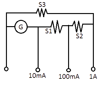
Ans: We can measure the currents of magnitude\[10mA\], \[100mA\] and \[1A\] by connecting the ammeter $A$ and$B$, $C$ and $D$ respectively. So,
For \[10mA\to {{I}_{g}}G=\left( I-{{I}_{g}} \right)\left( {{S}_{1}}+{{S}_{2}}+{{S}_{3}} \right)\] ……... (I)
For \[100mA\to {{I}_{g}}\left( G+{{S}_{1}} \right)=\left( I-{{I}_{g}} \right)\left( {{S}_{2}}+{{S}_{3}} \right)\]…….... (II)
For \[1A\to {{I}_{g}}\left( G+{{S}_{1}}+{{S}_{2}} \right)=\left( I-{{I}_{g}} \right){{S}_{3}}\] ……... (III)
\[{{I}_{g}}=1mA={{10}^{-3}}A\text{ }\]and \[G=10\Omega \]
\[{{10}^{-3}}\theta 10=\left( {{10}^{-2}}-{{10}^{-3}} \right)\left( {{S}_{1}}+{{S}_{2}}+{{S}_{3}}\text{ } \right)\] [From equation (I)]
\[\Rightarrow 10=\left( 10-1 \right)\left( {{S}_{1}}+{{S}_{2}}+{{S}_{3}} \right)\]
\[\Rightarrow 10=9\left( {{S}_{1}}+{{S}_{2}}+{{S}_{3}} \right)\] ……... (IV)
\[{{10}^{-3}}\left( 10+{{S}_{1}} \right)=\left( {{10}^{-1}}-{{10}^{-3}} \right)\left( {{S}_{2}}+{{S}_{3}} \right)\] [From equation (II)]
\[\Rightarrow 10+{{S}_{1}}=\left( 100-1 \right)\left( {{S}_{2}}+{{S}_{3}} \right)\]
\[\Rightarrow 10+{{S}_{1}}=99\left( {{S}_{2}}+{{S}_{3}} \right)\] …..... (V)
\[{{10}^{-3}}\left( 10+{{S}_{1}}+{{S}_{2}} \right)=\left( 1-{{10}^{-3}} \right)\left( {{S}_{3\text{ }}} \right)\] [From equation (III)]
\[\Rightarrow 10+{{S}_{1}}+{{S}_{2}}=\left( 1000-1 \right){{S}_{3}}\]
\[\Rightarrow 10+{{S}_{1}}+{{S}_{2}}=999{{S}_{3}}\] …..... (VI)
\[10+{{S}_{1}}=99\left( {{S}_{3}}+{{S}_{2}} \right)\] [From equation (V)]
\[10=9\left( {{S}_{3}}+{{S}_{2}}+{{S}_{1}} \right)\] [From equation (V)]
$\dfrac{10}{9}={{S}_{1}}+{{S}_{2}}+{{S}_{3}}$ [From equation (IV)]
$\dfrac{\dfrac{10}{-99}+\dfrac{{{S}_{1}}}{-99}=-{{S}_{2}}\pm {{S}_{3}}}{\dfrac{10}{9}-\dfrac{10}{99}-\dfrac{{{S}_{1}}}{99}={{S}_{1}}}$[From equation (V)]
$\dfrac{110-10}{99}={{S}_{1}}+\dfrac{{{S}_{1}}}{99}$
$\dfrac{100}{99}=\dfrac{99{{S}_{1}}+{{S}_{1}}}{99}\Rightarrow \dfrac{100}{99}=\dfrac{100}{99}{{S}_{1}}$
\[{{S}_{1}}=1\Omega \]
So $\dfrac{10}{9}=1+{{S}_{2}}+{{S}_{3}}$ [From equation (VI)]
Or $\dfrac{1}{9}={{S}_{2}}+{{S}_{3}}$
${{S}_{3}}=\dfrac{10}{999}+\dfrac{{{S}_{1}}}{999}+\dfrac{{{S}_{2}}}{999}$[From equation (VI)]
${{S}_{3}}=\dfrac{10}{999}+\dfrac{1}{999}+\dfrac{{{S}_{2}}}{999}$ \[\left[ \because {{S}_{1}}=1\Omega \right]\]
$\Rightarrow {{S}_{3}}=\dfrac{11}{999}+\dfrac{{{S}_{2}}}{999}$
${{S}_{2}}=\dfrac{1}{9}-{{S}_{3}}$ $\left[ \because \dfrac{1}{9}={{S}_{2}}+{{S}_{3\text{ }}}\text{from above} \right]$
$=\dfrac{1}{9}-\dfrac{11}{999}-\dfrac{{{S}_{2}}}{999}$ (From equation III)
${{S}_{2}}+\dfrac{{{S}_{2}}}{999}=\dfrac{111-11}{999}$
$\dfrac{1000}{999}{{S}_{2}}=\dfrac{100}{999}$
${{S}_{2}}=0.1\Omega $
${{S}_{1}}+{{S}_{2}}+{{S}_{3}}=\dfrac{10}{9}$ (From equation IV)
$\Rightarrow 0.1+0.1+{{S}_{3}}=\dfrac{10}{9}$
$\Rightarrow {{S}_{3}}=\dfrac{10}{9}-\dfrac{11}{10}=\dfrac{100-99}{90}=\dfrac{1}{90}$
Hence,$\,{{S}_{1}}=1\Omega $; \[{{S}_{2}}=0.1\Omega \]; \[{{S}_{3}}=0.01\Omega \]
4.29 Five long wires $A$, $B$, $C$, $D$ and $E$, each carrying current $I$are arranged to form edges of a pentagonal prism as shown in Fig. 4.6. Each carries current out of the plane of paper.
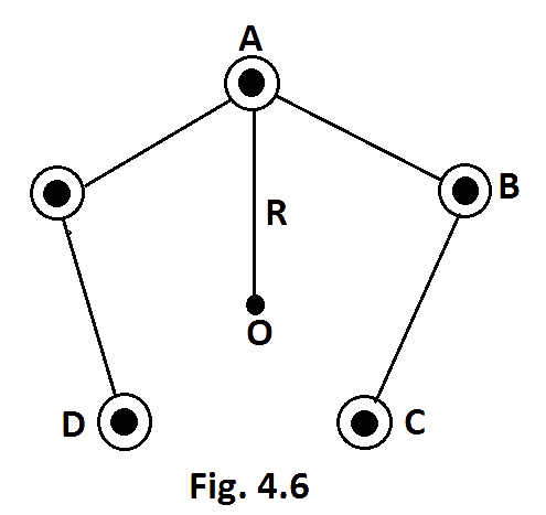
(a) What will be magnetic induction at a point on the axis$O$? Axis is at a distance $R$ from each wire.
(b) What will be the field if current in one of the wires (say A) is switched off?
(c) What if current in one of the wire (say) A is reversed?
Ans: (a) Figure shows that five conductors$AA'$, \[BB'\], \[CC'\], \[DD'\] and \[EE'\] are along height of regular pentagonal prism\[ABCDE\].
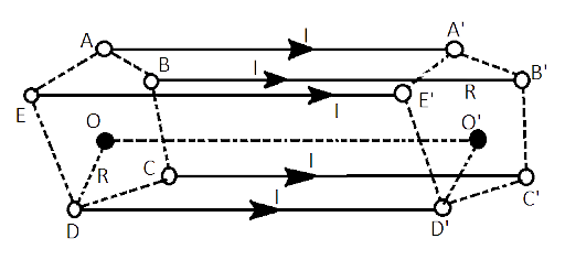
It is given that the five identical conducting wires are along the heights of regular pentagon, represented in figure above by$AA'$,\[BB'\],\[CC'\], \[DD'\], and\[EE'\]. Axis of regular pentagon is \[OO\] will be equidistant \[\left( R \right)\]from all five conductors, the current is passing through all five conductors are equal let\[\left( I \right)\].
As the current in all 5 conductors are equal to $I$ and the distance of $O$ from conductors is also equal to $R$ then the magnitude of a magnetic field due to each conductor will be equal, i.e.
$\left| {{B}_{1}} \right|=\left| {{B}_{2}} \right|=\left| {{B}_{3}} \right|=\left| {{B}_{4}} \right|=\left| {{B}_{5}} \right|=B=\dfrac{{{\mu }_{0}}I}{2\pi R}$
The direction of the magnetic field induced can be found out by the right-hand grip rule, then direction of the induced magnetic field at ‘$O$’ due to $AA'$ will be perpendicular to both $AA'$ and $AO$. Angles between any two consecutive magnetic field is $\dfrac{{{360}^{\circ }}}{5}={{72}^{\circ }}$
As shown in figures given below
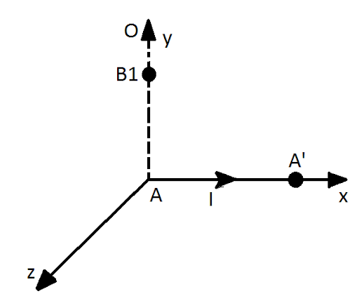
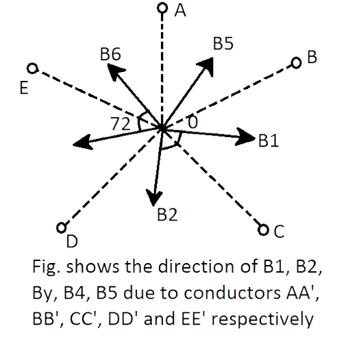
As, \[B={{B}_{1}}={{B}_{2}}={{B}_{3}}={{B}_{4}}={{B}_{5}}\]and the angle between consecutive magnetic fields is ${{72}^{\circ }}$or symmetric in${{360}^{\circ }}$ so their resultant at $O$ will be zero, i.e.
\[\overrightarrow{{{B}_{1}}}+\overrightarrow{{{B}_{2}}}+\overrightarrow{{{B}_{3}}}+\overrightarrow{{{B}_{4}}}+\overrightarrow{{{B}_{5}}}=0\]
Hence, the induced magnetic induction at $O$ due to the five conductors as shown in figure is zero.
(b) When current in $AA'$ is switched off, then \[{{B}_{1}}=0\]and resultant becomes
\[R={{B}_{2}}+{{B}_{3}}+{{B}_{4}}+{{B}_{5}}\]
But from (a) part, \[{{B}_{1}}+{{B}_{2}}+{{B}_{3}}+{{B}_{4}}+{{B}_{5}}=0\]
Or \[\overrightarrow{{{B}_{2}}}+\overrightarrow{{{B}_{3}}}+\overrightarrow{{{B}_{4}}}+\overrightarrow{{{B}_{5}}}=-\overrightarrow{{{B}_{1}}}\]
\[R=-{{B}_{1}}\]
$R=\dfrac{{{\mu }_{0}}I}{2\pi r}$
i.e. direction of resultant is opposite to${{\overrightarrow{B}}_{1}}$ .
(c) Here, on reversing the current in$AA'$, direction of magnetic field due to $AA'$ becomes $-{{\overrightarrow{B}}_{1}}$,
\[R={{B}_{2}}+{{B}_{3}}+{{B}_{4}}+{{B}_{5}}\]
$\because \left| -{{B}_{1}} \right|=\left| {{B}_{2}} \right|=\left| {{B}_{3}} \right|=\left| {{B}_{4}} \right|=\left| {{B}_{5}} \right|=B$
$\therefore $Net induced magnetic field at $O$ becomes
\[-B+B+B+B+B=3B\]
$R=\dfrac{3{{\mu }_{0}}I}{2\pi r}$
NCERT Exemplar for Class 12 Physics - Moving Charges And Magnetism
Physics Class 12 CBSE Exemplar Solutions is very important to study material. It is extremely helpful for the students who are searching for answers related to difficult questions and the techniques used to solve them.
By providing the NCERT Physics Class 12 Exemplar Solutions, Vedantu’s sole intention is to reach out to the students who require these study materials for their board examination and other entrance examinations preparation. Solutions make it easier to clear doubts and strengthen the understanding of a topic.
Topics covered in Class 12 Physics Chapter 4 Moving charges and Magnetism:
The topics that are covered in the Class 12 Physics Chapter 4 moving charges and magnetism can be provided as follows:
Magnetic force
Source and fields
Magnetic field and lorentz force
Motion in a magnetic field
Magnetic force on a current carrying conductor
Motion in a combined electric and magnetic fields
Velocity selector
Cyclotron
Ampere’s Circuital law
Magnetic field on the axis of a circular current loop
Force between two parallel currents
Torque on current look
Circular current loop as a magnetic dipole
Conclusion:
Vedantu is an online-based platform that provides various study materials for Classes 1 to 12 (CBSE and ICSE board examinations). All study material and assistance you require at any stage of your academic life can be found on Vedantu, the best part? Most of it is a free resource for students who simply sign up with us.
FAQs on NCERT Exemplar for Class 12 Physics Chapter-4 (Book Solutions)
1. How Does Solving Chapter 4 Moving Charge and Magnetism Exemplars benefit the Students of Physics Class 12 (CBSE)?
As we know, practice is the Key to Success. Chapter 4 Moving Charge and Magnetism is a chapter that consists of Direct Derivative Type Questions as well as Numerical Type Questions. Which is the reason why students of Physics Class 12 (CBSE) are required to practice as many examples as they can, To get prepared for any type of questions that might appear in the examinations. Students are suggested to solve every question from Chapter 4 Moving Charge and Magnetism, which is provided in their NCERT textbook. They can also refer to the solutions of the NCERT exemplars that are provided on Vedantu. Practising these exemplars is very important for the preparation of board examinations and other entrance examinations.
2. How to Study Physics Class 12, Chapter 4 Moving Charges and Magnetism from the NCERT textbook?
Chapter 4 Moving Charges and Magnetism is a huge chapter and hence, you will not be able to cover this chapter within a short time. Students generally require at least three days to complete this chapter and also to solve its Exemplars.
Some useful tips to learn this chapter:
Understand the concepts of each topic.
The chapter has lots of formulassoleranin the formulas accurately is very important.
Make a note of all the formulas and read everyday. You should also understand the derivation of the formulas in step.
Solve the problem with understanding.
As Class 12 Physics consists of mostly numercials that are particular to moving charges and magnetism it will be highly recommended to use the Vedantu NCERT Solutions for Class 12 physics which will help you understand the concepts well.
Start reading the NCERT textbook for Chapter 4 moving charges and magnetism which is available at Vedantu and the additional information that is provided.
After you have understood all the concepts related to Chapter 4 moving charges and magnetism, use the Vedantu Class 12 Physics previous years papers to solve the questions related to it.
3. What are some study assistance for Physics Class 12 CBSE students?
NCERT textbooks are highly recommended study material for Physics Class 12 (CBSE) examination. Students are recommended to study NCERT books thoroughly, they can also visit Vedantu for Physics Class 12 CBSE NCERT exemplar solutions. Vedantu also provides online Physics tuition classes for CBSE class 12th students.
Students can Join the Vedantu Tuition Class for Physics to learn the concepts from Vedantu's expert teachers.
Students can also refer to the sample paper and previous year’s question paper for better preparation for the examination. Sample papers and Previous year question papers are also available on Vedantu.
4. What are the concepts that are involved in the Class 12 Physics Chapter 4 moving charges and magnetism?
Moving charges and magnetism are one of the concepts that are important in order to understand the relation between magnetism and electricity. These charges are also the ones that are responsible for the effect of magnetism; however it is also seen that a charged particle will be able to produce an electrical and magnetic field without having any effect of acceleration. Some of the other concepts that are covered in theClass 12 Physics Chapter 4 moving charges and magnetism can be provided as follows:
The Solenoid and the Toroid
Magnetic field and its effects
Magnetic forces affecting the electric fields
Study of moving coil galvanometer
Ampere’s law of circuit.
5. What are some important tips to do well in Physics class 12 board examinations?
Following are some tips and tricks students can refer to:
Read the Physics Class 12 CBSE syllabus properly. Check the new chapter wise marking scheme for the year (2024-25)
Divide the syllabus according to your preference and prepare a timetable. Set some weekly and monthly study targets
Don't forget to take short breaks while studying for longer durations.
Devote more time to the topics that carry maximum marks.
Try to understand the logic behind the derivation, you should try to learn how one step leads to the other in the derivation.
Keep Revising - Even after studying a Chapter, do not turn a blind eye towards it and keep revising it so that you don't forget its basic concepts.
Solve as many sample papers and previous year question papers as you can to get in-depth inside of your flaws and strengths.
There is no shortcut to success, hard work is the only way to achieve good marks in Physics class 12th Board CBSE Examinations.


