


How Does Internal Resistance Affect the EMF of a Cell?
Electromotive force (EMF) and internal resistance are fundamental concepts in the study of electrical cells and batteries. These parameters determine the performance and efficiency of cells in electrical circuits, making them essential topics for students preparing for competitive exams such as JEE.
Definition of EMF and Internal Resistance
EMF, or electromotive force, is defined as the maximum potential difference between the terminals of a cell when no current is drawn from it. Internal resistance refers to the inherent resistance offered by the cell to the flow of current due to the nature of its electrolyte and materials. This resistance affects the actual voltage obtained from the cell during operation. For more foundational knowledge, refer to Current Electricity Overview.
Mathematical Expression and Circuit Representation
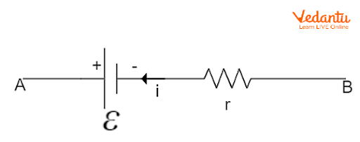
When a cell of EMF $\varepsilon$ and internal resistance $r$ is connected to an external load resistance $R$, current $I$ flows through the circuit. The terminal voltage $V$ across the cell is related to the EMF and the internal resistance by the equation $V = \varepsilon - Ir$, where $I$ is the current drawn from the cell.
The total current in the circuit can be derived using Ohm’s law and is given by $I = \dfrac{\varepsilon}{R + r}$. Here, $R$ is the resistance of the external circuit and $r$ is the internal resistance. An in-depth explanation of resistance is available in the article Understanding Resistance.
Relation Between EMF, Internal Resistance, and Terminal Voltage
The EMF represents the chemical energy converted into electrical energy per unit charge within the cell. However, the internal resistance $r$ causes a potential drop inside the cell, so the terminal voltage $V$ is less than the EMF when current is flowing. The relationship is expressed as $V = \varepsilon - Ir$, indicating that the terminal voltage decreases linearly with increasing current. For information about Ohm's law as applied to such circuits, see Ohm's Law and Its Applications.
Expression for Current in a Cell Circuit
When applying Kirchhoff’s law to a simple circuit consisting of a cell and an external resistor, the potential drop across the external resistor and the internal resistance together equal the EMF of the cell. The resulting equation is $\varepsilon = IR + Ir$, or $I = \dfrac{\varepsilon}{R + r}$. This equation is fundamental when analyzing circuits involving real cells.
Measurement of EMF and Internal Resistance Using Potentiometer
A potentiometer is a device used to measure the EMF of a cell accurately, as well as to determine its internal resistance. The principle is based on comparing potential differences without drawing current from the cell under test, eliminating errors due to internal resistance. Detailed applications and construction are provided in the article Electromagnetic Induction Basics.

To measure the EMF, the cell is connected to the potentiometer with no external load, and the potential difference is balanced against a length $l_1$ of potentiometer wire. The EMF is calculated as $\varepsilon = k l_1$, where $k$ is the potential gradient. When a known resistance is connected externally, the cell’s terminal voltage balances at $l_2$, and the ratio of lengths gives the internal resistance as $r = R \left(\dfrac{l_1}{l_2} - 1\right)$.

Factors Affecting Internal Resistance of a Cell
The internal resistance of a cell depends on several physical and chemical parameters such as the nature of electrolyte, distance between electrodes, and surface area of electrodes. Understanding these factors is important for optimizing cell efficiency in practical circuits, discussed further in Capacitors and Their Functions.
- Increased electrode area decreases internal resistance
- Greater electrode separation increases internal resistance
- Higher electrolyte concentration increases internal resistance
- Increased temperature decreases internal resistance
Comparison Table: EMF vs Internal Resistance
| Parameter | Description |
|---|---|
| EMF ($\varepsilon$) | Maximum possible cell voltage (no load) |
| Internal Resistance ($r$) | Obstruction to current within the cell |
| SI Unit of EMF | Volt (V) |
| SI Unit of Internal Resistance | Ohm (Ω) |
Graphical Representation
A graph between terminal voltage $V$ and current $I$ for a source of constant EMF and internal resistance is a straight line with negative slope. The intercept on the voltage axis gives the EMF, and the slope gives the value of internal resistance, illustrating their linear relationship.
Key Formulas
The following equations summarize the relationships among EMF, terminal voltage, internal resistance, and external resistance:
- EMF: $\varepsilon = \dfrac{W}{q}$
- Terminal voltage: $V = \varepsilon - Ir$
- Current: $I = \dfrac{\varepsilon}{R + r}$
- Internal resistance (using potentiometer): $r = R\left(\dfrac{l_1}{l_2} - 1\right)$
Application: Estimation of EMF and Internal Resistance
To experimentally determine the EMF and internal resistance of a cell, the potentiometer method is employed, ensuring no significant current is drawn during EMF measurement. During internal resistance determination, a known external resistance is switched in, and balance lengths are obtained for calculation.
Summary of Concepts
EMF is the energy supplied per unit charge by the cell, while internal resistance reduces the effective terminal voltage when current is drawn. Measurement techniques such as potentiometers provide precise values for these parameters in laboratory settings.
Further Reading
For advanced understanding of currents, fields, and resistance in circuits, refer to Electric Field from Charged Ring and consult resources on related JEE Main Physics topics.


FAQs on Understanding EMF and Internal Resistance of a Cell
1. What is EMF and internal resistance of a cell?
EMF (electromotive force) is the maximum potential difference between the terminals of a cell when no current is flowing, while internal resistance is the opposition offered by the cell to the flow of electric current within itself.
- EMF represents the energy supplied by the cell per coulomb of charge.
- Internal resistance depends on the nature and concentration of the electrolytes as well as the size of the electrodes.
- The terminal voltage decreases as current increases due to internal resistance.
2. How is the EMF of a cell different from the terminal potential difference?
EMF is the potential difference when no current flows, while terminal potential difference is the voltage measured when current flows through the cell.
- EMF is always higher than the terminal voltage due to internal resistance.
- Terminal voltage = EMF - (Current × Internal resistance)
3. How can you determine the internal resistance of a cell experimentally?
The internal resistance of a cell can be measured using a potentiometer or voltmeter by comparing the emf and terminal voltage under different loads.
- Measure the emf of the cell using a potentiometer (no current drawn).
- Connect a known resistance and measure the terminal voltage.
- Use the formula: r = (E - V)R / V, where:
E = EMF, V = Terminal voltage, R = External resistance, r = Internal resistance.
4. Why does the terminal voltage of a cell decrease when current flows through it?
The terminal voltage decreases as current flows because the cell’s internal resistance opposes the flow and causes a voltage drop inside the cell.
- Voltage drop across internal resistance = I × r (I = current, r = internal resistance)
- This reduces the effective voltage available at the terminals.
5. What is the formula relating EMF, internal resistance, and terminal voltage?
The relationship is given by the formula:
- Terminal voltage (V) = EMF (E) – Current (I) × Internal resistance (r)
- Or, V = E – Ir
- This is important for CBSE physics numericals and conceptual questions.
6. How does the internal resistance of a cell depend on its factors?
The internal resistance of a cell varies according to several factors:
- Increases with the distance between electrodes.
- Decreases with larger electrode area.
- Depends on the nature and concentration of the electrolyte.
- Increases with temperature if electrolyte resistance increases.
7. What happens to the EMF of a cell if its internal resistance increases?
The EMF (electromotive force) of a cell does not change with the internal resistance; EMF is a fixed value determined by the chemical reaction inside the cell. However, a higher internal resistance causes greater voltage drop when current flows, lowering the terminal voltage available to a circuit.
8. Why is the EMF of a cell nearly equal to the terminal voltage on open circuit?
When no current flows through the cell (open circuit), there is no voltage drop across the internal resistance, so the terminal voltage equals the EMF.
- Terminal voltage = EMF when current = 0.
- This is commonly tested in board exams and practicals.
9. How can you increase the terminal voltage delivered by a cell in a circuit?
To increase the terminal voltage delivered by a cell:
- Reduce the external current drawn from the cell.
- Decrease the cell’s internal resistance (by increasing electrolyte concentration or electrode area).
- Connect cells in parallel to reduce effective internal resistance.
10. What is a practical application of understanding the internal resistance of cells?
Understanding internal resistance is crucial in designing batteries for devices to ensure efficient energy transfer.
- Helps in selecting the right battery for electronic circuits.
- Important in maximizing terminal voltage and energy efficiency.
- Ensures battery performance meets the needs of devices like remotes, cameras, and vehicles.