


Pulse Code Modulation: An Introduction
You all must know that to share data or information over long ranges, we need to send it in the form of signals. Now, these signals might lose their strength, or there might be some external signal that can alter our original information. When we transmit information from source to receiver, a lot of delay, noise or data loss can be observed in the received signal. Sometimes, the transmitted signal's frequency also plays a vital role in its effective transmission.
To counter these problems, we use modulating techniques depending on our requirements, signal speed, the quantity of data transferred, etc. One such technique is called Pulse Code Modulation. This method comes under Digital Modulation, where a discrete signal modulates an analogue carrier signal (transformed).
What is PCM?
Modulation is used for the effective transmission of signals. One such known technique is Pulse Code Modulation. Through PCM, we can convert an analogue signal into a digital signal, whose amplitude is denoted by a binary sequence, and then demodulate it according to our needs. Using PCM, we can digitise all forms of analogue signals, including motion videos, music, etc.
History
Alec Reeves was a British scientist. Reeves was best known for his great invention of Pulse Code Modulation, which now proves to be useful in transmitting signals successfully without interference from external noise.
Alec Reeves
PCM Waveform
The figure below shows us the output waveform of a PCM signal where the input is an analog signal(a sine wave): (PCM Waveform)
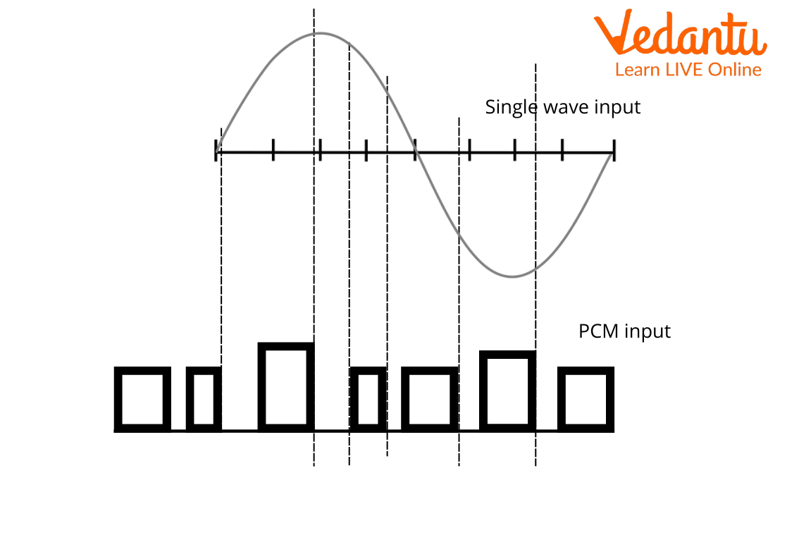
PCM waveform
The amplitude at any time of the PCM signal is given by a series of binary codes as shown in the figure below:
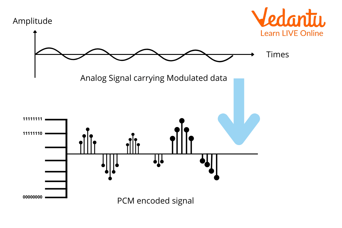
Binary coded amplitude of PCM
PCM Block Diagram
We start with our analogue signal and then proceed to the low-pass filter. It eliminates high-frequency components in the message signal. This is followed by the sampler, quantizer and then encoder.
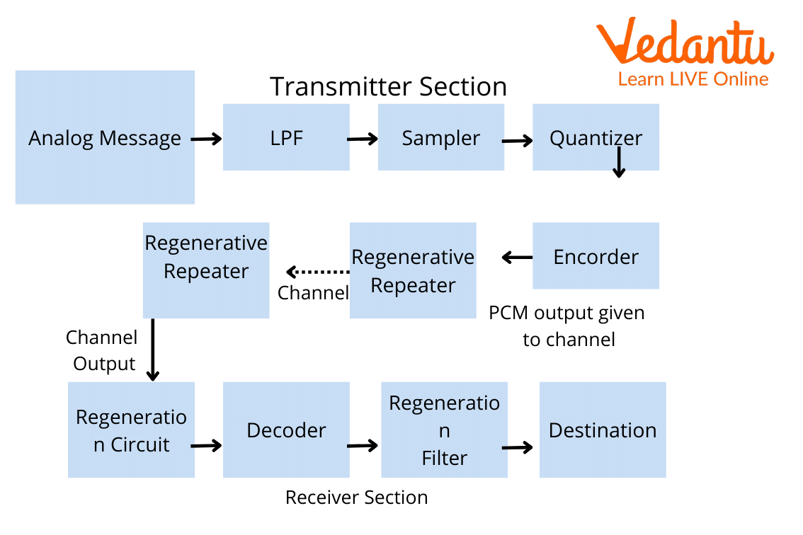
PCM block diagram
Low Pass Filter: Low pass filter helps to remove the high-frequency components which are included in the input of the provided analogue signal. These frequency components are higher than the highest frequency of the message signal. So, a low pass filter is added in the PCM technique to avoid the aliasing of message signals.
Sampler: The Sampler helps us to collect sample data at any time of the message signal, to reform the original signal. As per the sampling theorem, the sampling rate is higher than the highest frequency component of the message signal.
Quantizer: Quantizer helps us to minimise the errors through the processes and this is known as quantizing. When the sampled output passes through a quantizer, it reduces unnecessary bits and helps in compressing obtained values too.
Encoder: The encoder is used to digitise analogue signals. The encoder helps to allot a quantised level through a binary code. The sample-and-hold process is adopted in this. Low pass filter and sampler, and quantiser aid to convert the analogue signal to digital forms. Encoding also helps in minimising the use of bandwidth.
Regenerative Repeater: Regenerative repeater is used for compensating for signal loss and also to reform signal. It helps in increasing signal strength. So, the output of the channel is equipped with a regenerative repeater circuit.
Decoder: The decoder helps us in forming original signals by decoding pulse-coded waveforms. The decoder acts as a demodulator.
Reconstruction Filter: The reconstruction filter helps us to obtain the original signal. In the PCM circuit, the provided analogue signal is digitised, coded and sampled. The resultant signal is transmitted in the analogue form. To obtain the original signal, this whole process is repeated in a reverse pattern.
PCM: Advantages and Disadvantages
Applications of Pulse Code Modulation
It is used in long-distance communication like telephony.
PCM systems can also be used for space communication and satellite transmission systems.
Pulse Code Modulation is also being recently used in Compact Disks(CD).
Some Important Solved Questions
1. What are the steps involved in the transmitter section of the PCM?
Ans: The three steps involved are Sampling, Quantization and Encoding. Sampling measures the amplitude of a continuous time at discrete instants and then converts the continuous signal into a discrete signal. This is followed by quantization where only a defined set of quantized values are taken by amplitude. The third one comes with encoding, where the quantized samples are encoded.
2. What are the limitations of PCM?
Ans: For use of PCM, the user should have access to large bandwidth and also, an overload seems to appear when modulating signal changes between samplings by an amount greater than the size of the step.
3. Does PCM use codec?
Ans: Yes, PCM uses Coding-Decoding. It acts as an analogue-digital interface for voice band signals, designed with a combination of coders and decoders, thereby meeting the requirement for communication systems, including the cellular phone.
Summary
Modulation is nothing but transforming a signal to make it more efficient to transmit. PCM was invented by Alec Reeves, a British scientist, which converts analog signals into digital signals having amplitudes in the form of binary sequences. Next, we discussed several advantages and disadvantages of using PCM, followed by some real-life applications of PCM.
FAQs on Pulse Code Modulation
1. What is Linear Pulse Code Modulation?
It is denoted by LPCM. It is a specific type of Pulse Code Modulation in which the quantisation levels are uniform and linearly. This is a bit different from PCM in the fashion that in the Pulse Coding Modulation technique, the quantization levels vary as the function of the amplitude of the message signal that is being transmitted. Even though PCM is a more general term, we use it to describe the data which is encoded as Linear Pulse Code Modulation (LPCM).
2. How can you increase PCM signal strength?
Regenerative repeaters make up for the signal loss, in case the intensity of the message signal is hampered. The input repeater increases the signal strength to make up for the intensity loss, whereas the output repeater reconstructs the signal to increase its strength. It is very important to keep the signal strength high because if the signal strength drops, then the quantization noise becomes more noticeable, which interferes with the message signal, hence decreasing the quality of the received signal at the receiver’s end.
3. What is the maximum sampling frequency?
Sampling frequency defines the number of samples per second taken from a continuous signal to convert it into a digital signal with amplitudes represented by binary sequences. 48kHz sampling rate is the recommended frequency for most applications but, specifically speaking, 44.1kHz is for CDs and other customer usages, 32kHz for transmission-related applications and 96kHz for higher bandwidth usage. For telephony systems, a frequency of 8kHz has been set as the golden number all across the World.