


Draw the circuit diagram of AND gate using diodes.
Answer
584.7k+ views
Hint: Firstly, the working principle of AND gate has to be defined. The circuit diagram has to be
drawn using diodes and the working of the circuit has to be known.
An AND gate is a logic gate to perform a logic and operation where the output becomes true
when all the inputs are true. It can be two input or multi-input and only one output based on the
requirement. It is known as AND gate because the output is high only when all the inputs are high.
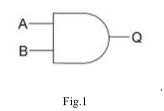
The symbol of AND gate is as shown below. A and B are the input terminals and Q is the output.
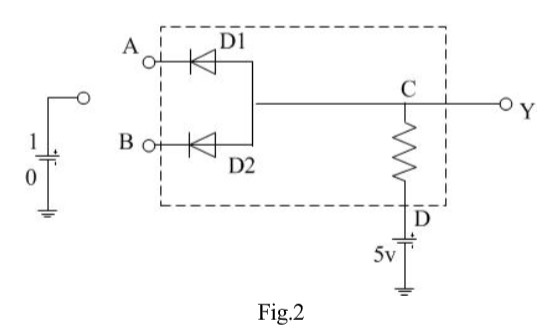
AND gate is an electrical circuit using diodes D1 and D2 as shown in Fig.2 in which the switches A
and B are connected in series with diodes and a resistor is used in the output side as a pull down
resistance to the ground. Y is the output terminal. Since it is a logic circuit hence, $0$ means zero
input and $1$ means input is high i.e. the switches are in ON condition.
The working principle can be explained as, when supply is given to the circuit and switches A and B
are closed then only a current will flow and the output terminal gives an output. There are four cases
which explains the working of the circuit.
Case(i) if $A = 0$and$B = 0$i.e. switches A and B are off, both diodes are in forward bias condition
and they conduct and hence the output will be zero, because the supply voltage will be dropped
across load only. Therefore $Y = 0$.
Case(ii) if $A = 0$ and $B = 1$. When $B = 0$ and B is high, diode D1 is forward biased and diode
D2 is reverse biased. The diode D1 will now conduct due to forward biasing. Therefore, output $Y =
0$.
Case(iii) if $A = 1$ and $B = 0$.
In this case, diode D2 will be conducting and hence the output $Y = 0$.
Case(iv) $A = 1$and$B = 1$.
In this case, both the diodes are not conducting. Since D1 and D2 are in OFF condition, no current
flows through the load. The output is equal to the supply voltage. Therefore, output, $Y = 1$.
Thus the output will be high only when the inputs A and B are high.
Note: In the solution, the students need to understand the principle and definition of AND logic
gate. The circuit representation using diodes has to be drawn. The logic of input and output has
to be known. The conditions of switching and what output is obtained when input is high or low
has to be identified from the circuit.
drawn using diodes and the working of the circuit has to be known.
An AND gate is a logic gate to perform a logic and operation where the output becomes true
when all the inputs are true. It can be two input or multi-input and only one output based on the
requirement. It is known as AND gate because the output is high only when all the inputs are high.
The symbol of AND gate is as shown below. A and B are the input terminals and Q is the output.
AND gate is an electrical circuit using diodes D1 and D2 as shown in Fig.2 in which the switches A
and B are connected in series with diodes and a resistor is used in the output side as a pull down
resistance to the ground. Y is the output terminal. Since it is a logic circuit hence, $0$ means zero
input and $1$ means input is high i.e. the switches are in ON condition.
The working principle can be explained as, when supply is given to the circuit and switches A and B
are closed then only a current will flow and the output terminal gives an output. There are four cases
which explains the working of the circuit.
Case(i) if $A = 0$and$B = 0$i.e. switches A and B are off, both diodes are in forward bias condition
and they conduct and hence the output will be zero, because the supply voltage will be dropped
across load only. Therefore $Y = 0$.
Case(ii) if $A = 0$ and $B = 1$. When $B = 0$ and B is high, diode D1 is forward biased and diode
D2 is reverse biased. The diode D1 will now conduct due to forward biasing. Therefore, output $Y =
0$.
Case(iii) if $A = 1$ and $B = 0$.
In this case, diode D2 will be conducting and hence the output $Y = 0$.
Case(iv) $A = 1$and$B = 1$.
In this case, both the diodes are not conducting. Since D1 and D2 are in OFF condition, no current
flows through the load. The output is equal to the supply voltage. Therefore, output, $Y = 1$.
Thus the output will be high only when the inputs A and B are high.
Note: In the solution, the students need to understand the principle and definition of AND logic
gate. The circuit representation using diodes has to be drawn. The logic of input and output has
to be known. The conditions of switching and what output is obtained when input is high or low
has to be identified from the circuit.
Recently Updated Pages
Master Class 10 Computer Science: Engaging Questions & Answers for Success
Master Class 10 General Knowledge: Engaging Questions & Answers for Success
Master Class 10 English: Engaging Questions & Answers for Success
Master Class 10 Social Science: Engaging Questions & Answers for Success
Master Class 10 Maths: Engaging Questions & Answers for Success
Master Class 10 Science: Engaging Questions & Answers for Success
Trending doubts
What is the median of the first 10 natural numbers class 10 maths CBSE
Which women's tennis player has 24 Grand Slam singles titles?
Who is the Brand Ambassador of Incredible India?
Why is there a time difference of about 5 hours between class 10 social science CBSE
Write a letter to the principal requesting him to grant class 10 english CBSE
A moving boat is observed from the top of a 150 m high class 10 maths CBSE