


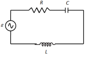
Figure shows a series LCR circuit connected to a variable frequency 230 V source. \[L = 5.0\,{\text{H}}\], \[C = 80\,\mu F\], \[R = 40\,\Omega \].
(a) Determine the source frequency which drives the circuit in resonance.
(b) Obtain the impedance of the circuit and the amplitude of current at the resonating frequency.
(c) Determine the rms potential drop across the three elements of the circuit. Show that the potential drop across the LC combination is zero at the resonating frequency.
Answer
567.9k+ views
Hint: At resonance, the inductive reactance and capacitive reactance becomes equal. Use this fact to determine the impedance of the circuit. The amplitude of the current in an LCR circuit is the ratio of peak voltage to impedance of the circuit. The voltage drop across each component is equal to the product of total current and reactance of that element.
Formula used:
Resonating frequency in the LC circuit,
\[\omega = \dfrac{1}{{\sqrt {LC} }}\]
Here, L is the inductor and C is the capacitor.
Impedance of the series LCR circuit is given as,
\[Z = \sqrt {{R^2} + {{\left( {{X_L} - {X_C}} \right)}^2}} \]
Here, \[{X_L}\] is the inductive reactance and \[{X_C}\] is the capacitive reactance.
Complete step by step answer:
We have given, \[L = 5.0\,{\text{H}}\], \[C = 80\,\mu F\], \[R = 40\,\Omega \].
(a) We have the expression for the resonating frequency in the LC circuit,
\[\omega = \dfrac{1}{{\sqrt {LC} }}\]
Here, L is the inductor and C is the capacitor.
Substituting \[L = 5.0\,{\text{H}}\] and \[C = 80\,\mu F\] in the above equation, we get,
\[\omega = \dfrac{1}{{\sqrt {\left( 5 \right)\left( {80 \times {{10}^{ - 6}}} \right)} }}\]
\[ \Rightarrow \omega = \dfrac{1}{{0.02}}\]
\[ \Rightarrow \omega = 50\,{\text{rad/s}}\]
Therefore, the source frequency which drives the circuit in resonance is 50 rad/s.
(b) We know that at resonance, the capacitive reactance and inductive reactance are equal. Therefore, \[{X_L} = {X_C}\]
Here, \[{X_L}\] is the inductive reactance and \[{X_C}\] is the capacitive reactance.
We have the impedance of the series LCR circuit is given as,
\[Z = \sqrt {{R^2} + {{\left( {{X_L} - {X_C}} \right)}^2}} \]
Substituting \[{X_L} = {X_C}\] in the above equation, we get,
\[Z = \sqrt {{R^2} + {{\left( {{X_C} - {X_C}} \right)}^2}} \]
\[ \Rightarrow Z = \sqrt {{R^2}} \]
\[ \Rightarrow Z = R\]
\[ \Rightarrow Z = 40\,\Omega \]
Therefore, the impedance of the circuit is \[40\,\Omega \].
We have the expression for the amplitude of the current in LCR circuit is,
\[{I_0} = \dfrac{{{V_0}}}{Z}\]
Here, \[{V_0}\] is the peak voltage and it is given as,
\[{V_0} = \sqrt 2 V\], where V is the source voltage.
Therefore, the amplitude of the current becomes,
\[{I_0} = \dfrac{{\sqrt 2 V}}{Z}\]
\[ \Rightarrow {I_0} = \dfrac{{\sqrt 2 \left( {230} \right)}}{{40}}\]
\[ \Rightarrow {I_0} = 8.13\,{\text{A}}\]
Therefore, the amplitude of the current is 8.13 A.
(c) Let’s find the total current in the circuit as,
\[I = \dfrac{{{I_0}}}{{\sqrt 2 }}\]
\[ \Rightarrow I = \dfrac{{8.13}}{{\sqrt 2 }}\]
\[ \Rightarrow I = 5.75\,{\text{A}}\]
Now, we know that the potential drop across the inductor is given as,
\[{V_L} = I \times \omega L\] , where, \[\omega \] is the resonance frequency.
Substituting 5.75 A for I, 50 rad/s for \[\omega \] and 5.0 H for L in the above equation, we get,
\[{V_L} = \left( {5.75} \right) \times \left( {50} \right)\left( 5 \right)\]
\[ \Rightarrow {V_L} = 1437.5\,{\text{V}}\]
We have the potential drop across the capacitor is given as,
\[{V_C} = I \times \dfrac{1}{{\omega C}}\]
Substituting 5.75 A for I, 50 rad/s for \[\omega \] and \[80\,\mu F\] for C in the above equation, we get,
\[{V_C} = \left( {5.75} \right) \times \dfrac{1}{{\left( {50} \right)\left( {80 \times {{10}^{ - 6}}} \right)}}\]
\[ \Rightarrow {V_C} = \left( {5.75} \right) \times \left( {250} \right)\]
\[ \Rightarrow {V_C} = 1437.5\,{\text{V}}\]
The voltage drop across the resistor is given as,
\[{V_R} = I \times R\]
Substituting 5.75 A for I and \[40\,\Omega \] for R in the above equation, we get,
\[{V_R} = \left( {5.75} \right) \times \left( {40} \right)\]
\[ \Rightarrow {V_R} = 230\,{\text{V}}\]
We have the potential drop across the LC circuit is given as,
\[{V_{LC}} = I\left( {{X_L} - {X_C}} \right)\]
As we have seen earlier, at resonance, \[{X_L} = {X_C}\].
Therefore, the potential drop across the LC combination becomes zero.
Note:The potential drop across the LC circuit at resonance is zero and therefore,\[{V_{LC}} = I\left( {{X_L} - {X_C}} \right) = I{X_L} - I{X_C} = 0\]
\[ \Rightarrow I{X_L} = I{X_C}\]
\[ \Rightarrow {V_L} = {V_C}\]
Therefore, the potential drop across both inductor and capacitor is the same at resonance as we see in the solution.At resonance, the impedance of the whole circuit that is resistance in the LCR circuit is only due to the resistor.
Recently Updated Pages
Master Class 12 Economics: Engaging Questions & Answers for Success
Master Class 12 Physics: Engaging Questions & Answers for Success
Master Class 12 English: Engaging Questions & Answers for Success
Master Class 12 Social Science: Engaging Questions & Answers for Success
Master Class 12 Maths: Engaging Questions & Answers for Success
Master Class 12 Business Studies: Engaging Questions & Answers for Success
Trending doubts
Which are the Top 10 Largest Countries of the World?
What are the major means of transport Explain each class 12 social science CBSE
Draw a labelled sketch of the human eye class 12 physics CBSE
Why cannot DNA pass through cell membranes class 12 biology CBSE
Differentiate between insitu conservation and exsitu class 12 biology CBSE
Draw a neat and well labeled diagram of TS of ovary class 12 biology CBSE