


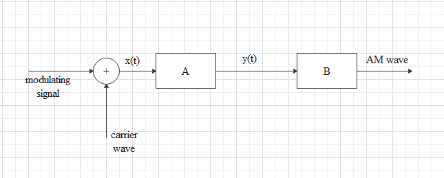
In the block diagram of a simple modulator for obtaining an AM signal shown in the figure, identify the boxes A and B.
Write their functions,
Answer
603k+ views
Hint: Study about the modulators and how they work. By observing the diagram imagine which component will be used in this instrument. Study the components of a AM modulator or amplitude modulator.
Complete step by step answer:
We are given a diagram of a simple modulator for obtaining AM signal. We can complete the diagram as,
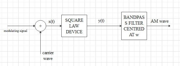
The box A is the square law device and the box B is the bandpass filter.
A modulator can modulate the input signal. In AM modulation (amplitude modulation) we make the signals shorter or longer to add signal to it.
A square law device can be identified as a device which produces output voltage or current which is directly proportional to the square of the input voltage or current respectively. These devices are mainly used in modulators and detectors. This is a non-linear device and produces non-linear output of the input signals.
A filter is an electronic circuit which is capable of passing certain frequencies while it can cut off the other frequencies. A band pass filter can be defined as a filter which can allow frequencies within a specific range while attenuating the frequencies which are outside this range.
Note: The square law device is a non-linear device, i.e. the input and output signal of this device do not have any linear relation. In this device the input voltage will be squared and given as an output value.
We have many other filters such as low pass filter which passes the low frequency signals only or high pass filter which passes high frequency signal only. Here, we use the band pass filter which is used to block the signals which are outside the range of a particular frequency.
Complete step by step answer:
We are given a diagram of a simple modulator for obtaining AM signal. We can complete the diagram as,
The box A is the square law device and the box B is the bandpass filter.
A modulator can modulate the input signal. In AM modulation (amplitude modulation) we make the signals shorter or longer to add signal to it.
A square law device can be identified as a device which produces output voltage or current which is directly proportional to the square of the input voltage or current respectively. These devices are mainly used in modulators and detectors. This is a non-linear device and produces non-linear output of the input signals.
A filter is an electronic circuit which is capable of passing certain frequencies while it can cut off the other frequencies. A band pass filter can be defined as a filter which can allow frequencies within a specific range while attenuating the frequencies which are outside this range.
Note: The square law device is a non-linear device, i.e. the input and output signal of this device do not have any linear relation. In this device the input voltage will be squared and given as an output value.
We have many other filters such as low pass filter which passes the low frequency signals only or high pass filter which passes high frequency signal only. Here, we use the band pass filter which is used to block the signals which are outside the range of a particular frequency.
Recently Updated Pages
Master Class 12 Economics: Engaging Questions & Answers for Success
Master Class 12 Physics: Engaging Questions & Answers for Success
Master Class 12 English: Engaging Questions & Answers for Success
Master Class 12 Social Science: Engaging Questions & Answers for Success
Master Class 12 Maths: Engaging Questions & Answers for Success
Master Class 12 Business Studies: Engaging Questions & Answers for Success
Trending doubts
Which are the Top 10 Largest Countries of the World?
What are the major means of transport Explain each class 12 social science CBSE
Draw a labelled sketch of the human eye class 12 physics CBSE
Why cannot DNA pass through cell membranes class 12 biology CBSE
Differentiate between insitu conservation and exsitu class 12 biology CBSE
Draw a neat and well labeled diagram of TS of ovary class 12 biology CBSE