


In the figure shown, Rheostat works as
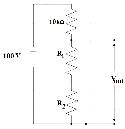
(Desired range for ${{V}_{out}}$ = 30 volts to 70 volts)
A. Voltage divider
B. Current regulator
C. Inductor
D. Capacitor
Answer
584.7k+ views
Hint: Recall the various applications of a rheostat. See whether you could identify which of those applications is used in the given figure. If not, try to think of how the rheostat works. Also, understand what change happens to the circuit when the jockey of rheostat is adjusted.
Complete step by step answer:
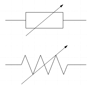
We know that, Rheostat is basically a variable resistor, that is, its resistance can be changed which further results in change in the amount of current flowing through the circuit. The very name of the component comes from two Greek words ‘rheos’ and ‘statis’ which together means a current controlling device. They have at most three terminals just like a potentiometer. However, only two of these terminals are used. Wire wound resistors are used in their construction since they have to carry a significant amount of current. It is normally represented either of the following symbols,
Rheostats can be used as both voltage divider and current regulator. If you want to determine whether the rheostat acts as a voltage divider or current regulator from your first glimpse at the circuit, you could look at how the output source is connected. If the output source is connected in series with the rheostat, the rheostat there acts as a current regulator instead if the output source is connected in parallel with the rheostat, you can be sure that the rheostat there acts as a voltage divider. So, from the figure, it is very clear that rheostat is acting as a voltage divider in the circuit since the output source is parallel to it.
Let us understand the working of a rheostat as a voltage divider better. For that let us use a cylindrical resistor of 12Ω across the 24V battery.
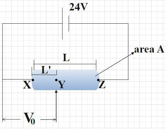
When the output source is connected across X and Z, ohm's law is given by,
$V=IR$
$V=I\left( \rho \dfrac{L}{A} \right)$
$\Rightarrow I=\dfrac{VA}{\rho L}$ …………………… (1)
Where, ρ is the resistivity.
Now if the jockey was moved from X to Z, output voltage is ${{V}_{0}}$ which given by,
${{V}_{0}}=I\left( \rho \dfrac{L'}{A} \right)$ ……………………… (2)
Current for a series circuit remains the same throughout and hence even when the jockey is moved, the current is the same I.
Substituting (1) in (2),
${{V}_{0}}=\left( \dfrac{VA}{\rho L} \right)\left( \dfrac{\rho L'}{A} \right)$
$\Rightarrow {{V}_{0}}=V\dfrac{L'}{L}$
$\Rightarrow {{V}_{0}}\propto L'$
Hence, we realize that output voltage is directly proportional to the length, so, we are able to vary the voltage from 0V to 24V just by changing the position of the jockey (that is, by varying the length).
So let us summarize all the above facts. By varying the resistance, rheostat controls the voltage. Since the voltage remains equal for a parallel connection, changing the jockey position can change the output voltage. Also note that the output source should be parallel with the rheostat.
Therefore, in the given figure the rheostat works as a voltage divider as the output source is in parallel with the rheostat.
So, the correct answer is “Option A”.
Note: We know that rheostat is also used as a current regulator and to regulate current, we have to see that the output source is connected in series with the rheostat. By doing so, as we slide the jockey the current increases depending on the length of the conductor in which current is flowing. Some of the applications are in adjusting the speed of fan, temperature of heater and brightness of bulb.
Complete step by step answer:
We know that, Rheostat is basically a variable resistor, that is, its resistance can be changed which further results in change in the amount of current flowing through the circuit. The very name of the component comes from two Greek words ‘rheos’ and ‘statis’ which together means a current controlling device. They have at most three terminals just like a potentiometer. However, only two of these terminals are used. Wire wound resistors are used in their construction since they have to carry a significant amount of current. It is normally represented either of the following symbols,
Rheostats can be used as both voltage divider and current regulator. If you want to determine whether the rheostat acts as a voltage divider or current regulator from your first glimpse at the circuit, you could look at how the output source is connected. If the output source is connected in series with the rheostat, the rheostat there acts as a current regulator instead if the output source is connected in parallel with the rheostat, you can be sure that the rheostat there acts as a voltage divider. So, from the figure, it is very clear that rheostat is acting as a voltage divider in the circuit since the output source is parallel to it.
Let us understand the working of a rheostat as a voltage divider better. For that let us use a cylindrical resistor of 12Ω across the 24V battery.
When the output source is connected across X and Z, ohm's law is given by,
$V=IR$
$V=I\left( \rho \dfrac{L}{A} \right)$
$\Rightarrow I=\dfrac{VA}{\rho L}$ …………………… (1)
Where, ρ is the resistivity.
Now if the jockey was moved from X to Z, output voltage is ${{V}_{0}}$ which given by,
${{V}_{0}}=I\left( \rho \dfrac{L'}{A} \right)$ ……………………… (2)
Current for a series circuit remains the same throughout and hence even when the jockey is moved, the current is the same I.
Substituting (1) in (2),
${{V}_{0}}=\left( \dfrac{VA}{\rho L} \right)\left( \dfrac{\rho L'}{A} \right)$
$\Rightarrow {{V}_{0}}=V\dfrac{L'}{L}$
$\Rightarrow {{V}_{0}}\propto L'$
Hence, we realize that output voltage is directly proportional to the length, so, we are able to vary the voltage from 0V to 24V just by changing the position of the jockey (that is, by varying the length).
So let us summarize all the above facts. By varying the resistance, rheostat controls the voltage. Since the voltage remains equal for a parallel connection, changing the jockey position can change the output voltage. Also note that the output source should be parallel with the rheostat.
Therefore, in the given figure the rheostat works as a voltage divider as the output source is in parallel with the rheostat.
So, the correct answer is “Option A”.
Note: We know that rheostat is also used as a current regulator and to regulate current, we have to see that the output source is connected in series with the rheostat. By doing so, as we slide the jockey the current increases depending on the length of the conductor in which current is flowing. Some of the applications are in adjusting the speed of fan, temperature of heater and brightness of bulb.
Recently Updated Pages
Master Class 12 Economics: Engaging Questions & Answers for Success
Master Class 12 Physics: Engaging Questions & Answers for Success
Master Class 12 English: Engaging Questions & Answers for Success
Master Class 12 Social Science: Engaging Questions & Answers for Success
Master Class 12 Maths: Engaging Questions & Answers for Success
Master Class 12 Business Studies: Engaging Questions & Answers for Success
Trending doubts
Which are the Top 10 Largest Countries of the World?
What are the major means of transport Explain each class 12 social science CBSE
Draw a labelled sketch of the human eye class 12 physics CBSE
Why cannot DNA pass through cell membranes class 12 biology CBSE
Differentiate between insitu conservation and exsitu class 12 biology CBSE
Draw a neat and well labeled diagram of TS of ovary class 12 biology CBSE