


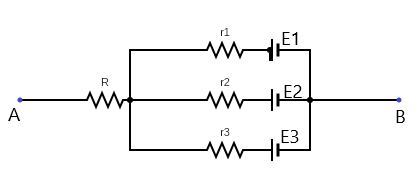
In the network shown, the potential difference between A and B is:
($R = {r_1} = {r_2} = {r_3} = 1\Omega, {E_1} = 3V,{E_2} = 2V,{E_3} = 1V$)
(A) 1V
(B) 2V
(C) 3V
(D) 4V
Answer
573.3k+ views
Hint
Resistance $R$ is not connected to a closed circuit. The resistors ${r_1}$, ${r_2}$ and ${r_3}$ are configured in parallel. Thus, current flowing through one of them doesn’t have to flow through the others.
Formula used: $V = IR$ where $V$ is the potential difference across the points considered, $I$ is current, and $R$ is resistance.
$\dfrac{1}{{{R_{eq}}}} = \dfrac{1}{{{r_1}}} + \dfrac{1}{{{r_2}}} + \dfrac{1}{{{r_3}}}$ where ${R_{eq}}$ is the equivalent resistance of the parallel resistors ${r_1}$, ${r_2}$ and ${r_3}$.
Complete step by step answer
The resistors ${r_1}$, ${r_2}$ and ${r_3}$ are in parallel configuration. Thus, Ohm’s law can be applied to each of the resistors. This is because parallel resistors loop back on themselves without its current passing through the other resistors. No current flows through resistor R since it’s not part of a complete loop, thus an open circuit.
An alternate way to draw the circuit above is shown below.
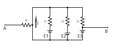
From the diagram above, it is clear that current can pass through the resistor ${r_1}$ without passing through ${r_2}$ and ${r_3}$.
Similarly for the resistor${r_2}$ and ${r_3}$.
For current passing through ${r_1}$ we can use ohm’s law, i.e.
${E_1} = {I_1}{r_1}$
$ \Rightarrow {I_1} = \dfrac{{{E_1}}}{{{r_1}}}$
Substituting the values in the question, we have
${I_1} = \dfrac{3}{1} = 3A$
Similarly for ${r_2}$,
$ \Rightarrow {I_2} = \dfrac{2}{1} = 2A$
And finally for ${r_3}$,
${I_3} = \dfrac{1}{1} = 1A$
Now, let us find the total current flowing in the circuit. This is given as
$I = {I_1} + {I_2} + {I_3}$
Substituting each values into the formula, we have
$I = 3 + 2 + 1 = 6A$
Next, let’s calculate the equivalent resistance of the parallel connections. This is given as
$\dfrac{1}{{{R_{eq}}}} = \dfrac{1}{{{r_1}}} + \dfrac{1}{{{r_2}}} + \dfrac{1}{{{r_3}}}$
Substituting their respective values
$\dfrac{1}{{{R_{eq}}}} = \dfrac{1}{1} + \dfrac{1}{1} + \dfrac{1}{1} = 1 + 1 + 1$
$ \Rightarrow \dfrac{1}{{{R_{eq}}}} = 3$
By inverting both sides we get,
${R_{eq}} = \dfrac{1}{3}\Omega $
Finally, the potential difference between A and B is
$PD = I{R_{eq}}$
Therefore, by substituting
$PD = 6 \times \dfrac{1}{3}$
$\therefore PD = 2V$
Hence, the correct option is B.
Note
A point of confusion is why no current flows through resistance $R$ despite being part of the circuit. To understand this more clearly, observe that the point AB is open, i.e. the current doesn’t flow from A to B. It can be considered as a stray wire (which may be connected to a voltmeter or similar devices). Thus all current flow within the parallel configuration, and that is all is needed to be analyzed.
Resistance $R$ is not connected to a closed circuit. The resistors ${r_1}$, ${r_2}$ and ${r_3}$ are configured in parallel. Thus, current flowing through one of them doesn’t have to flow through the others.
Formula used: $V = IR$ where $V$ is the potential difference across the points considered, $I$ is current, and $R$ is resistance.
$\dfrac{1}{{{R_{eq}}}} = \dfrac{1}{{{r_1}}} + \dfrac{1}{{{r_2}}} + \dfrac{1}{{{r_3}}}$ where ${R_{eq}}$ is the equivalent resistance of the parallel resistors ${r_1}$, ${r_2}$ and ${r_3}$.
Complete step by step answer
The resistors ${r_1}$, ${r_2}$ and ${r_3}$ are in parallel configuration. Thus, Ohm’s law can be applied to each of the resistors. This is because parallel resistors loop back on themselves without its current passing through the other resistors. No current flows through resistor R since it’s not part of a complete loop, thus an open circuit.
An alternate way to draw the circuit above is shown below.
From the diagram above, it is clear that current can pass through the resistor ${r_1}$ without passing through ${r_2}$ and ${r_3}$.
Similarly for the resistor${r_2}$ and ${r_3}$.
For current passing through ${r_1}$ we can use ohm’s law, i.e.
${E_1} = {I_1}{r_1}$
$ \Rightarrow {I_1} = \dfrac{{{E_1}}}{{{r_1}}}$
Substituting the values in the question, we have
${I_1} = \dfrac{3}{1} = 3A$
Similarly for ${r_2}$,
$ \Rightarrow {I_2} = \dfrac{2}{1} = 2A$
And finally for ${r_3}$,
${I_3} = \dfrac{1}{1} = 1A$
Now, let us find the total current flowing in the circuit. This is given as
$I = {I_1} + {I_2} + {I_3}$
Substituting each values into the formula, we have
$I = 3 + 2 + 1 = 6A$
Next, let’s calculate the equivalent resistance of the parallel connections. This is given as
$\dfrac{1}{{{R_{eq}}}} = \dfrac{1}{{{r_1}}} + \dfrac{1}{{{r_2}}} + \dfrac{1}{{{r_3}}}$
Substituting their respective values
$\dfrac{1}{{{R_{eq}}}} = \dfrac{1}{1} + \dfrac{1}{1} + \dfrac{1}{1} = 1 + 1 + 1$
$ \Rightarrow \dfrac{1}{{{R_{eq}}}} = 3$
By inverting both sides we get,
${R_{eq}} = \dfrac{1}{3}\Omega $
Finally, the potential difference between A and B is
$PD = I{R_{eq}}$
Therefore, by substituting
$PD = 6 \times \dfrac{1}{3}$
$\therefore PD = 2V$
Hence, the correct option is B.
Note
A point of confusion is why no current flows through resistance $R$ despite being part of the circuit. To understand this more clearly, observe that the point AB is open, i.e. the current doesn’t flow from A to B. It can be considered as a stray wire (which may be connected to a voltmeter or similar devices). Thus all current flow within the parallel configuration, and that is all is needed to be analyzed.
Recently Updated Pages
Master Class 12 Economics: Engaging Questions & Answers for Success
Master Class 12 Physics: Engaging Questions & Answers for Success
Master Class 12 English: Engaging Questions & Answers for Success
Master Class 12 Social Science: Engaging Questions & Answers for Success
Master Class 12 Maths: Engaging Questions & Answers for Success
Master Class 12 Business Studies: Engaging Questions & Answers for Success
Trending doubts
Which are the Top 10 Largest Countries of the World?
What are the major means of transport Explain each class 12 social science CBSE
Draw a labelled sketch of the human eye class 12 physics CBSE
Why cannot DNA pass through cell membranes class 12 biology CBSE
Differentiate between insitu conservation and exsitu class 12 biology CBSE
Draw a neat and well labeled diagram of TS of ovary class 12 biology CBSE