


What is meant by half-power point frequencies? Obtain an expression for bandwidth in a LCR series circuit. Show half power point frequencies in a curve between alternating current and frequency.
Answer
588.6k+ views
Hint: Bandwidth is the difference in the half power frequencies. To obtain an expression for bandwidth, find the values of the half power frequencies. Find the current when the power is half of the maximum in terms of the maximum current. Use $V={{i}_{\max }}R$ and ${{Z}^{2}}={{R}^{2}}+{{\left( 2\pi fL-\dfrac{1}{2\pi fC} \right)}^{2}}$.
Formula used:
$V={{i}_{\max }}R$
${{Z}^{2}}={{R}^{2}}+{{\left( 2\pi fL-\dfrac{1}{2\pi fC} \right)}^{2}}$
Complete answer:
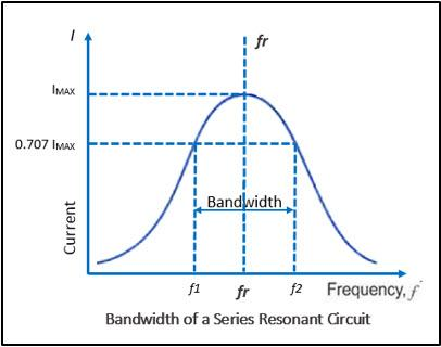
Half power points frequencies for a given LCR are the frequencies for which the power in the circuit is half of the maximum power in the circuit.
The current in the circuit at maximum power is also maximum. Let it be ${{i}_{max}}$.
Maximum current is obtained at resonance. At resonance, the frequency of the circuit is called resonance frequency (${{f}_{0}}$).
Every circuit has two half power frequencies ${{f}_{1}}$ and ${{f}_{2}}$.
The impedance of the circuit is Z=R.
Therefore, at resonance$V={{i}_{\max }}R$.
$\Rightarrow {{i}_{\max }}=\dfrac{V}{R}$ …. (i).
And the power is ${{P}_{max}}=i_{\max }^{2}R$
At the half frequencies, power of the circuit is $P=\dfrac{{{P}_{max}}}{2}=\dfrac{i_{\max }^{2}R}{2}={{\left( \dfrac{{{i}_{\max }}}{\sqrt{2}} \right)}^{2}}R$.
This means that the current in the circuit at half power frequencies is $\dfrac{{{i}_{\max }}}{\sqrt{2}}$.
Then, $V=\dfrac{{{i}_{\max }}}{\sqrt{2}}Z$.
Substitute the value of ${{i}_{max}}$ from (i).
$\Rightarrow V=\dfrac{\left( \dfrac{V}{R} \right)}{\sqrt{2}}Z$
$\Rightarrow \sqrt{2}R=Z$
$\Rightarrow 2{{R}^{2}}={{Z}^{2}}$
But, ${{Z}^{2}}={{R}^{2}}+{{\left( 2\pi fL-\dfrac{1}{2\pi fC} \right)}^{2}}$
Therefore,
$\Rightarrow 2{{R}^{2}}={{R}^{2}}+{{\left( 2\pi fL-\dfrac{1}{2\pi fC} \right)}^{2}}$
$\Rightarrow {{R}^{2}}={{\left( 2\pi fL-\dfrac{1}{2\pi fC} \right)}^{2}}$
$\Rightarrow R=\pm \left( 2\pi fL-\dfrac{1}{2\pi fC} \right)$
This proves that there are two values of half power frequencies.
Therefore,
$R=2\pi {{f}_{1}}L-\dfrac{1}{2\pi {{f}_{1}}C}$ or $R=\dfrac{1}{2\pi {{f}_{2}}C}-2\pi {{f}_{2}}L$.
$\Rightarrow R=\dfrac{4{{\pi }^{2}}f_{1}^{2}LC-1}{2\pi {{f}_{1}}C}$
$\Rightarrow 2\pi {{f}_{1}}CR=4{{\pi }^{2}}f_{1}^{2}LC-1$ ….. (iii).
And
$\Rightarrow R=\dfrac{1-4{{\pi }^{2}}f_{2}^{2}LC}{2\pi {{f}_{2}}C}$
$\Rightarrow 2\pi {{f}_{2}}CR=1-4{{\pi }^{2}}f_{2}^{2}LC$ ….. (iv).
Add (iii) and (iv).
$\Rightarrow 2\pi {{f}_{1}}CR+2\pi {{f}_{2}}CR=4{{\pi }^{2}}f_{1}^{2}LC-1+1-4{{\pi }^{2}}f_{2}^{2}LC$
$\Rightarrow \left( {{f}_{1}}+{{f}_{2}} \right)R=2\pi \left( f_{1}^{2}-f_{2}^{2} \right)L$
$\Rightarrow \left( {{f}_{1}}+{{f}_{2}} \right)R=2\pi \left( {{f}_{1}}+{{f}_{2}} \right)\left( {{f}_{1}}-{{f}_{2}} \right)L$
$\Rightarrow \left( {{f}_{1}}-{{f}_{2}} \right)=\dfrac{R}{2\pi L}$.
The difference in the half power frequencies i.e. $\left( {{f}_{1}}-{{f}_{2}} \right)$, is called bandwidth.
Therefore, we found an expression for the bandwidth.
The curve of alternating current with respect to the frequency of the source is shown below.
Note:
The value of bandwidth can also be found if we know the expression for the quality factor (Q) of a given circuit. The quality factor is defined as $Q=\dfrac{{{f}_{0}}}{BW}$, ${{f}_{0}}$ is the resonance frequency of the LCR circuit and BW is the bandwidth of the circuit.
The quality factor is also given as $Q=\dfrac{2\pi {{f}_{0}}L}{R}$.
$\Rightarrow Q=\dfrac{{{f}_{0}}}{BW}=\dfrac{2\pi {{f}_{0}}L}{R}$
$\Rightarrow \dfrac{1}{BW}=\dfrac{2\pi L}{R}$
$\Rightarrow BW=\dfrac{R}{2\pi L}$.
Formula used:
$V={{i}_{\max }}R$
${{Z}^{2}}={{R}^{2}}+{{\left( 2\pi fL-\dfrac{1}{2\pi fC} \right)}^{2}}$
Complete answer:
Half power points frequencies for a given LCR are the frequencies for which the power in the circuit is half of the maximum power in the circuit.
The current in the circuit at maximum power is also maximum. Let it be ${{i}_{max}}$.
Maximum current is obtained at resonance. At resonance, the frequency of the circuit is called resonance frequency (${{f}_{0}}$).
Every circuit has two half power frequencies ${{f}_{1}}$ and ${{f}_{2}}$.
The impedance of the circuit is Z=R.
Therefore, at resonance$V={{i}_{\max }}R$.
$\Rightarrow {{i}_{\max }}=\dfrac{V}{R}$ …. (i).
And the power is ${{P}_{max}}=i_{\max }^{2}R$
At the half frequencies, power of the circuit is $P=\dfrac{{{P}_{max}}}{2}=\dfrac{i_{\max }^{2}R}{2}={{\left( \dfrac{{{i}_{\max }}}{\sqrt{2}} \right)}^{2}}R$.
This means that the current in the circuit at half power frequencies is $\dfrac{{{i}_{\max }}}{\sqrt{2}}$.
Then, $V=\dfrac{{{i}_{\max }}}{\sqrt{2}}Z$.
Substitute the value of ${{i}_{max}}$ from (i).
$\Rightarrow V=\dfrac{\left( \dfrac{V}{R} \right)}{\sqrt{2}}Z$
$\Rightarrow \sqrt{2}R=Z$
$\Rightarrow 2{{R}^{2}}={{Z}^{2}}$
But, ${{Z}^{2}}={{R}^{2}}+{{\left( 2\pi fL-\dfrac{1}{2\pi fC} \right)}^{2}}$
Therefore,
$\Rightarrow 2{{R}^{2}}={{R}^{2}}+{{\left( 2\pi fL-\dfrac{1}{2\pi fC} \right)}^{2}}$
$\Rightarrow {{R}^{2}}={{\left( 2\pi fL-\dfrac{1}{2\pi fC} \right)}^{2}}$
$\Rightarrow R=\pm \left( 2\pi fL-\dfrac{1}{2\pi fC} \right)$
This proves that there are two values of half power frequencies.
Therefore,
$R=2\pi {{f}_{1}}L-\dfrac{1}{2\pi {{f}_{1}}C}$ or $R=\dfrac{1}{2\pi {{f}_{2}}C}-2\pi {{f}_{2}}L$.
$\Rightarrow R=\dfrac{4{{\pi }^{2}}f_{1}^{2}LC-1}{2\pi {{f}_{1}}C}$
$\Rightarrow 2\pi {{f}_{1}}CR=4{{\pi }^{2}}f_{1}^{2}LC-1$ ….. (iii).
And
$\Rightarrow R=\dfrac{1-4{{\pi }^{2}}f_{2}^{2}LC}{2\pi {{f}_{2}}C}$
$\Rightarrow 2\pi {{f}_{2}}CR=1-4{{\pi }^{2}}f_{2}^{2}LC$ ….. (iv).
Add (iii) and (iv).
$\Rightarrow 2\pi {{f}_{1}}CR+2\pi {{f}_{2}}CR=4{{\pi }^{2}}f_{1}^{2}LC-1+1-4{{\pi }^{2}}f_{2}^{2}LC$
$\Rightarrow \left( {{f}_{1}}+{{f}_{2}} \right)R=2\pi \left( f_{1}^{2}-f_{2}^{2} \right)L$
$\Rightarrow \left( {{f}_{1}}+{{f}_{2}} \right)R=2\pi \left( {{f}_{1}}+{{f}_{2}} \right)\left( {{f}_{1}}-{{f}_{2}} \right)L$
$\Rightarrow \left( {{f}_{1}}-{{f}_{2}} \right)=\dfrac{R}{2\pi L}$.
The difference in the half power frequencies i.e. $\left( {{f}_{1}}-{{f}_{2}} \right)$, is called bandwidth.
Therefore, we found an expression for the bandwidth.
The curve of alternating current with respect to the frequency of the source is shown below.
Note:
The value of bandwidth can also be found if we know the expression for the quality factor (Q) of a given circuit. The quality factor is defined as $Q=\dfrac{{{f}_{0}}}{BW}$, ${{f}_{0}}$ is the resonance frequency of the LCR circuit and BW is the bandwidth of the circuit.
The quality factor is also given as $Q=\dfrac{2\pi {{f}_{0}}L}{R}$.
$\Rightarrow Q=\dfrac{{{f}_{0}}}{BW}=\dfrac{2\pi {{f}_{0}}L}{R}$
$\Rightarrow \dfrac{1}{BW}=\dfrac{2\pi L}{R}$
$\Rightarrow BW=\dfrac{R}{2\pi L}$.
Recently Updated Pages
Master Class 12 Economics: Engaging Questions & Answers for Success
Master Class 12 Physics: Engaging Questions & Answers for Success
Master Class 12 English: Engaging Questions & Answers for Success
Master Class 12 Social Science: Engaging Questions & Answers for Success
Master Class 12 Maths: Engaging Questions & Answers for Success
Master Class 12 Business Studies: Engaging Questions & Answers for Success
Trending doubts
Why cannot DNA pass through cell membranes class 12 biology CBSE
Differentiate between insitu conservation and exsitu class 12 biology CBSE
Draw a neat and well labeled diagram of TS of ovary class 12 biology CBSE
In a human foetus the limbs and digits develop after class 12 biology CBSE
AABbCc genotype forms how many types of gametes a 4 class 12 biology CBSE
The correct structure of ethylenediaminetetraacetic class 12 chemistry CBSE