


State Biot Savart law. Use this law to obtain a formula for magnetic field at the centre of a circular loop of radius R, number of turns N carrying current I. Sketch the magnetic field lines for a current loop clearly indicating the direction of the field.
Answer
568.5k+ views
Hint: Biot Savart law gives the magnitude of magnetic field due to current flowing through the current element at a certain distance from the current element. Consider the circular loop of wire of radius R and I be the current flowing through the circular loop and calculate the magnetic field at the centre using Biot Savart law. The circumference of the loop is \[2\pi R\].
Complete answer:
Biot Savart law is used to determine the magnetic field by the current carrying element. Biot Savart law states that the magnetic field induction due to a small current element is proportional to the current in that element, length of the element, sine of angle between the direction of length element and distance from the current element. Also it is inversely proportional to the square of the distance between the length element and the point where we want to calculate the magnetic field. We can express Biot Savart law as,
\[dB = \dfrac{{{\mu _0}}}{{4\pi }}\dfrac{{Idl\sin \theta }}{{{r^2}}}\]
Here, \[{\mu _0}\] is the permeability of the free space, I is the current through the length element \[dl\] and r is the distance between the length element and the point where we want to calculate the magnetic field.
Let’s consider the circular loop of wire of radius R and I be the current flowing through the circular loop. We assume that the circular loop is formed of a number of small length elements each of length \[dl\] forming the complete loop as shown in the figure below.
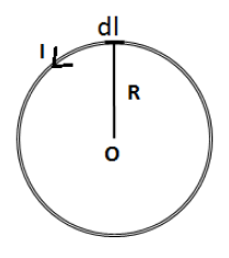
Let’s express the magnetic field at the centre of the circular loop due to current in the small length element \[dl\] using the Biot Savart law as follows,
\[dB = \dfrac{{{\mu _0}}}{{4\pi }}\dfrac{{Idl\sin \theta }}{{{R^2}}}\]
From the figure, we have the angle between \[d\vec l\] and \[\vec R\] is \[90^\circ \]. Therefore, the above equation becomes,
\[dB = \dfrac{{{\mu _0}}}{{4\pi }}\dfrac{{Idl\left( 1 \right)}}{{{R^2}}}\]
\[ \Rightarrow dB = \dfrac{{{\mu _0}}}{{4\pi }}\dfrac{{Idl}}{{{R^2}}}\]
Now, we can express the magnetic field at the centre of the loop due to current in the whole circular loop by integrating the above equation.
\[\int {dB} = B = \dfrac{{{\mu _0}I}}{{4\pi {R^2}}}\int {dl} \]
Here, the term \[\int {dl} \] is the total length of the circular wire. We know that this length is the circumference of the loop. Therefore, \[\int {dl} = 2\pi R\].
\[B = \dfrac{{{\mu _0}I}}{{4\pi {R^2}}}\left( {2\pi R} \right)\]
\[ \Rightarrow B = \dfrac{{{\mu _0}I}}{{2R}}\]
If we have N turns of the circular loop. The magnetic field at the centre of the loop becomes,
\[B = \dfrac{{{\mu _0}NI}}{{2R}}\]
This is our required expression.
We can show the magnetic lines due to current in the circular loop as shown in the figure below,
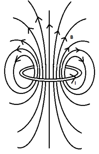
We have used the Right-hand thumb rule to determine the direction of the magnetic field. The magnetic field is pointing outward as shown in the figure when the direction of current in the loop is counter clockwise.
Note:The term \[\int {dl} \] represents the total length of the circular loop. The total length of the circle is always equal to\[2\pi R\], where R is the radius of the circle. To determine the direction of the magnetic field, don’t use Fleming’s left hand rule since we don’t know the direction of force yet. If you only know the direction of current then the direction of the magnetic field can be determined using Right-hand thumb rule.
Complete answer:
Biot Savart law is used to determine the magnetic field by the current carrying element. Biot Savart law states that the magnetic field induction due to a small current element is proportional to the current in that element, length of the element, sine of angle between the direction of length element and distance from the current element. Also it is inversely proportional to the square of the distance between the length element and the point where we want to calculate the magnetic field. We can express Biot Savart law as,
\[dB = \dfrac{{{\mu _0}}}{{4\pi }}\dfrac{{Idl\sin \theta }}{{{r^2}}}\]
Here, \[{\mu _0}\] is the permeability of the free space, I is the current through the length element \[dl\] and r is the distance between the length element and the point where we want to calculate the magnetic field.
Let’s consider the circular loop of wire of radius R and I be the current flowing through the circular loop. We assume that the circular loop is formed of a number of small length elements each of length \[dl\] forming the complete loop as shown in the figure below.
Let’s express the magnetic field at the centre of the circular loop due to current in the small length element \[dl\] using the Biot Savart law as follows,
\[dB = \dfrac{{{\mu _0}}}{{4\pi }}\dfrac{{Idl\sin \theta }}{{{R^2}}}\]
From the figure, we have the angle between \[d\vec l\] and \[\vec R\] is \[90^\circ \]. Therefore, the above equation becomes,
\[dB = \dfrac{{{\mu _0}}}{{4\pi }}\dfrac{{Idl\left( 1 \right)}}{{{R^2}}}\]
\[ \Rightarrow dB = \dfrac{{{\mu _0}}}{{4\pi }}\dfrac{{Idl}}{{{R^2}}}\]
Now, we can express the magnetic field at the centre of the loop due to current in the whole circular loop by integrating the above equation.
\[\int {dB} = B = \dfrac{{{\mu _0}I}}{{4\pi {R^2}}}\int {dl} \]
Here, the term \[\int {dl} \] is the total length of the circular wire. We know that this length is the circumference of the loop. Therefore, \[\int {dl} = 2\pi R\].
\[B = \dfrac{{{\mu _0}I}}{{4\pi {R^2}}}\left( {2\pi R} \right)\]
\[ \Rightarrow B = \dfrac{{{\mu _0}I}}{{2R}}\]
If we have N turns of the circular loop. The magnetic field at the centre of the loop becomes,
\[B = \dfrac{{{\mu _0}NI}}{{2R}}\]
This is our required expression.
We can show the magnetic lines due to current in the circular loop as shown in the figure below,
We have used the Right-hand thumb rule to determine the direction of the magnetic field. The magnetic field is pointing outward as shown in the figure when the direction of current in the loop is counter clockwise.
Note:The term \[\int {dl} \] represents the total length of the circular loop. The total length of the circle is always equal to\[2\pi R\], where R is the radius of the circle. To determine the direction of the magnetic field, don’t use Fleming’s left hand rule since we don’t know the direction of force yet. If you only know the direction of current then the direction of the magnetic field can be determined using Right-hand thumb rule.
Recently Updated Pages
Master Class 12 Economics: Engaging Questions & Answers for Success
Master Class 12 Physics: Engaging Questions & Answers for Success
Master Class 12 English: Engaging Questions & Answers for Success
Master Class 12 Social Science: Engaging Questions & Answers for Success
Master Class 12 Maths: Engaging Questions & Answers for Success
Master Class 12 Business Studies: Engaging Questions & Answers for Success
Trending doubts
Which are the Top 10 Largest Countries of the World?
What are the major means of transport Explain each class 12 social science CBSE
Draw a labelled sketch of the human eye class 12 physics CBSE
What is a transformer Explain the principle construction class 12 physics CBSE
Why cannot DNA pass through cell membranes class 12 biology CBSE
Differentiate between insitu conservation and exsitu class 12 biology CBSE