


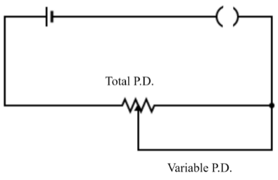
The arrangement as shown in the figure is called as ?
Answer
517.5k+ views
Hint: In the given diagram there is a voltage source, a key to close or open the circuit and a resistor. Also, there is one more wire which is connecting the circuit to a point that is somewhere in the middle of the resistor, which is labeled as ‘variable P.D’.
Complete answer:
Electrical circuits are closed paths in which electric current flows. A typical circuit includes a voltage or current source, a resistor or a device of some resistance value and other electrical or electronic devices such as capacitor, inductor, transmitter etc.
An electrical circuit of resistors has two basic forms, series combination or parallel combination.In a series combination, the electric current through the resistors is the same while the voltage across them is different; while in a parallel combination, the voltage across the resistors is the same but the current flowing through them is different.
Suppose many resistors are connected in series with each other and then to a voltage source, then the voltage across all of them gets divided in such a way that the voltage across any resistor \[{{R}_{x}}\] is given by: \[{{V}_{x}}(t)=V(t)\dfrac{{{R}_{x}}}{{{R}_{T}}}\], where \[{{R}_{T}}\] is the total resistance of the series combination. Voltage dividers are used for making potentiometers; in fact, they are also used in a wheat-stone bridge circuit and multimeter circuit.
Note: When a wire connects the voltage source to the resistor in such a way that one end of the wire divides the resistor into two parts, then basically the wire divides a single resistor into the combination of two series resistors, and since we know that in a series circuit the voltage gets divided across the resistors, that’s why the arrangement in the given figure is called as a voltage divider.
Recently Updated Pages
Master Class 12 Economics: Engaging Questions & Answers for Success
Master Class 12 Physics: Engaging Questions & Answers for Success
Master Class 12 English: Engaging Questions & Answers for Success
Master Class 12 Social Science: Engaging Questions & Answers for Success
Master Class 12 Maths: Engaging Questions & Answers for Success
Master Class 12 Business Studies: Engaging Questions & Answers for Success
Trending doubts
Which are the Top 10 Largest Countries of the World?
What are the major means of transport Explain each class 12 social science CBSE
Draw a labelled sketch of the human eye class 12 physics CBSE
What is a transformer Explain the principle construction class 12 physics CBSE
Why cannot DNA pass through cell membranes class 12 biology CBSE
Differentiate between insitu conservation and exsitu class 12 biology CBSE