


You are given three circuit elements X, Y and Z. When the element X is connected across an a.c. source of a given voltage, the current and the voltage are in the same phase. When the element Y is connected in series with X across the source, voltage is ahead of the current in phase by $\dfrac{\pi}{4}$ . But the current is ahead of the voltage in phase by $\dfrac{\pi}{4}$ when Z is connected in series with X across the source. Identify the circuit elements X, Y and Z.
Answer
507k+ views
Hint: We know that the source of an AC circuit is sinusoidal. Then there is a phase difference between the voltage and current. If the phase difference between the current and voltage is zero, then both are said to be in phase, and if the phase difference is not equal to zero, then both are said to be out of phase.
Complete answer:
A LCR circuit is where the inductor $L$ , capacitance $C$ and resistance $R$ are connected to an AC source. Here the LCR is connected in series circuit. Then the phase difference between the current and the voltage is $90^{\circ}$.
Let us consider that X,Y,Z are connected to the ac source as described in the question.
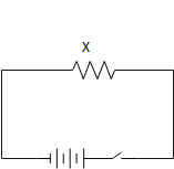
Given that when X is connected the phase angle between current and voltage is zero. Thus we can say that X is resistor, as shown in the image below
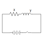
Similarly, given that when X and Y is connected in series the phase angle between current and voltage is not zero, and that current is ahead voltage, then we can say that Y is inductor, as shown in the image below
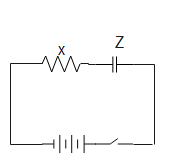
Similarly, given that when X and Z are connected in series the phase angle between current and voltage is not zero, and that current lags behind voltage, then we can say that Z is a capacitor, as shown in the image below.
Note: Resonance is observed when RLC is connected in series; here there is no phase difference between the current and the voltage. For frequency less than the resonant frequency, the impedance is capacitive in nature and for frequency greater than the resonant frequency; the impedance is inductive in nature.
Complete answer:
A LCR circuit is where the inductor $L$ , capacitance $C$ and resistance $R$ are connected to an AC source. Here the LCR is connected in series circuit. Then the phase difference between the current and the voltage is $90^{\circ}$.
Let us consider that X,Y,Z are connected to the ac source as described in the question.
Given that when X is connected the phase angle between current and voltage is zero. Thus we can say that X is resistor, as shown in the image below
Similarly, given that when X and Y is connected in series the phase angle between current and voltage is not zero, and that current is ahead voltage, then we can say that Y is inductor, as shown in the image below
Similarly, given that when X and Z are connected in series the phase angle between current and voltage is not zero, and that current lags behind voltage, then we can say that Z is a capacitor, as shown in the image below.
Note: Resonance is observed when RLC is connected in series; here there is no phase difference between the current and the voltage. For frequency less than the resonant frequency, the impedance is capacitive in nature and for frequency greater than the resonant frequency; the impedance is inductive in nature.
Recently Updated Pages
Master Class 12 Economics: Engaging Questions & Answers for Success
Master Class 12 Physics: Engaging Questions & Answers for Success
Master Class 12 English: Engaging Questions & Answers for Success
Master Class 12 Social Science: Engaging Questions & Answers for Success
Master Class 12 Maths: Engaging Questions & Answers for Success
Master Class 12 Business Studies: Engaging Questions & Answers for Success
Trending doubts
Which are the Top 10 Largest Countries of the World?
What are the major means of transport Explain each class 12 social science CBSE
Draw a labelled sketch of the human eye class 12 physics CBSE
Why cannot DNA pass through cell membranes class 12 biology CBSE
Differentiate between insitu conservation and exsitu class 12 biology CBSE
Draw a neat and well labeled diagram of TS of ovary class 12 biology CBSE