


What is a circuit diagram? Draw the labelled diagram of an electric circuit consisting of a cell, an ammeter, a voltmeter, and a closed switch (or closed plug key). Which of the two has a large resistance: an ammeter or a voltmeter?
Answer
569.1k+ views
Hint : To answer this question, we have to analyse the function of the ammeter and the voltmeter. Then on the basis of that we need to predict their position in an electric circuit with the help of which we can compare their resistances.
Complete answer
A circuit diagram is a pictorial representation of the connection of different components, which are indicated by the electrical symbols.
The different components of a circuit have their separate conventional symbols. So the required circuit diagram is represented as below.
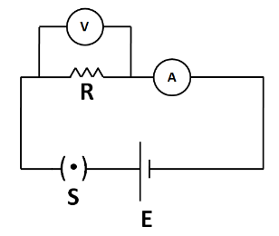
Here E is the cell, A is the ammeter, V is the voltmeter, S is the switch, which is closed, and R is the resistor. The Ammeter is used for measuring the current flowing in the circuit. That’s why it has been connected in series. Also, the voltmeter is used for measuring the potential difference between two points in a circuit. So it has been connected in parallel combination with the resistor.
As already explained above, an ammeter is connected in series to measure the current. So it must have a negligible resistance so that its presence does not affect the original value of the current flowing in the circuit to an appreciable amount. In the ideal case, an ammeter has a zero resistance.
Also, a voltmeter is always connected in parallel for measuring the potential difference across any two points in the circuit. So it must have very large resistance so that a negligible fraction of the original current flowing in the circuit goes into the voltmeter. In the ideal case a voltmeter has an infinite resistance.
Hence, a voltmeter has a larger resistance than an ammeter.
Note
Although in the question, we were not asked to include the resistor in the circuit diagram, we have to include it as it is an important element of an electric circuit. Without any resistance, the cell will become short circuited, and hence the circuit will not function. So a resistor must be included in an electric circuit.
Complete answer
A circuit diagram is a pictorial representation of the connection of different components, which are indicated by the electrical symbols.
The different components of a circuit have their separate conventional symbols. So the required circuit diagram is represented as below.
Here E is the cell, A is the ammeter, V is the voltmeter, S is the switch, which is closed, and R is the resistor. The Ammeter is used for measuring the current flowing in the circuit. That’s why it has been connected in series. Also, the voltmeter is used for measuring the potential difference between two points in a circuit. So it has been connected in parallel combination with the resistor.
As already explained above, an ammeter is connected in series to measure the current. So it must have a negligible resistance so that its presence does not affect the original value of the current flowing in the circuit to an appreciable amount. In the ideal case, an ammeter has a zero resistance.
Also, a voltmeter is always connected in parallel for measuring the potential difference across any two points in the circuit. So it must have very large resistance so that a negligible fraction of the original current flowing in the circuit goes into the voltmeter. In the ideal case a voltmeter has an infinite resistance.
Hence, a voltmeter has a larger resistance than an ammeter.
Note
Although in the question, we were not asked to include the resistor in the circuit diagram, we have to include it as it is an important element of an electric circuit. Without any resistance, the cell will become short circuited, and hence the circuit will not function. So a resistor must be included in an electric circuit.
Recently Updated Pages
Master Class 12 Economics: Engaging Questions & Answers for Success
Master Class 12 Physics: Engaging Questions & Answers for Success
Master Class 12 English: Engaging Questions & Answers for Success
Master Class 12 Social Science: Engaging Questions & Answers for Success
Master Class 12 Maths: Engaging Questions & Answers for Success
Master Class 12 Business Studies: Engaging Questions & Answers for Success
Trending doubts
Which are the Top 10 Largest Countries of the World?
What are the major means of transport Explain each class 12 social science CBSE
Draw a labelled sketch of the human eye class 12 physics CBSE
Why cannot DNA pass through cell membranes class 12 biology CBSE
Differentiate between insitu conservation and exsitu class 12 biology CBSE
Draw a neat and well labeled diagram of TS of ovary class 12 biology CBSE